Epson Stylus Pro 9000 Service Manual - Page 100
Connecting the carriage FFCs to the relay circuit board, Resetting the printer
 |
View all Epson Stylus Pro 9000 manuals
Add to My Manuals
Save this manual to your list of manuals |
Page 100 highlights
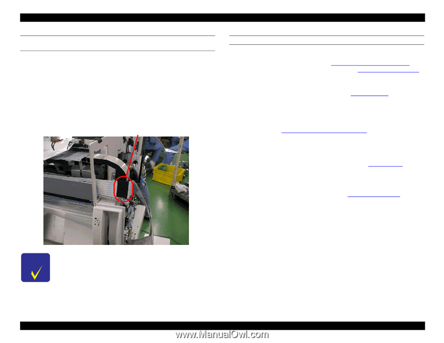
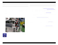
EPSON Stylus Pro 9000 CONNECTING THE CARRIAGE FFCS TO THE RELAY CIRCUIT BOARD 1. Peel off the backing of the double-sided adhesive tape at two places: the wall surface toward the right frame and the folded section near the center. 2. Make sure the FFCs are aligned and peel off the backing of the doublesided adhesive tape on the second FFC. Attach the second FFC to the back of the first one. 3. Fold the FFCs into three sections as shown below, and attach acetate rayon tape. 4. Connect the FFCs to the relay board connectors. Acetate rayon tape RESETTING THE PRINTER 1. Install new ink cartridges in the printer. 2. Enter the Self-Diagnostic Mode (see Using the Self-Diagnostic Mode on page 108) and adjust the capping position (see Cap Position Adjustment on page 116). After the printer automatically adjusts the cap position (a number appears on the LCD), press the Enter button on the control panel. 3. Perform an initial ink charge ("Init. Fill" in the Cleaning menu on page 128 of the Self-Diagnostic Mode). Check the ink discharge condition as well as the amount of ink in the dampers. Make sure there are no bubbles, which would indicate a leak in the ink delivery system. 4. Attach the carriage cover and perform the carriage cover height adjustment. See Carriage Cover Height Adjustment on page 130. 5. Lower the Paper Release Lever to prevent damage to the Paper Thickness Sensor, and then re-attach the Top Cover, being careful not to bump the sensor. 6. Load 44 inch roll paper and print a test pattern (see Check Nozzle on page 118). Check the operation of the printer, and make sure the order of printed colors in the check nozzle pattern is B, C, M, Y, LM, LC from the left. 7. Enter Maintenance Mode 2 as described in Maintenance Mode 2 on page 17. Then reset the Ink Counter ("Init. Ink") and CR Motor Counter ("Init. CR Motor"). As shown in the photo above, make sure the FFC does not block the tube guide assembly from moving all the way to the right. Disassembly & Assembly 100
-
 1
1 -
2
-
3
-
4
-
5
-
6
-
7
-
8
-
9
-
10
-
11
-
12
-
13
-
14
-
15
-
16
-
17
-
18
-
19
-
20
-
21
-
22
-
23
-
24
-
25
-
26
-
27
-
28
-
29
-
30
-
31
-
32
-
33
-
34
-
35
-
36
-
37
-
38
-
39
-
40
-
41
-
42
-
43
-
44
-
45
-
46
-
47
-
48
-
49
-
50
-
51
-
52
-
53
-
54
-
55
-
56
-
57
-
58
-
59
-
60
-
61
-
62
-
63
-
64
-
65
-
66
-
67
-
68
-
69
-
70
-
71
-
72
-
73
-
74
-
75
-
76
-
77
-
78
-
79
-
80
-
81
-
82
-
83
-
84
-
85
-
86
-
87
-
88
-
89
-
90
-
91
-
92
-
93
-
94
-
 95
95 -
 96
96 -
 97
97 -
 98
98 -
 99
99 -
 100
100 -
 101
101 -
 102
102 -
 103
103 -
 104
104 -
 105
105 -
106
-
107
-
108
-
109
-
110
-
111
-
112
-
113
-
114
-
115
-
116
-
117
-
118
-
119
-
120
-
121
-
122
-
123
-
124
-
125
-
126
-
127
-
128
-
129
-
130
-
131
-
132
-
133
-
134
-
135
-
136
-
137
-
138
-
139
-
140
-
141
-
142
-
143
-
144
-
145
-
146
-
147
-
148
-
149
-
150
-
151
-
152
-
153
-
154
-
155
-
156
-
157
-
158
-
159
-
160
-
161
-
162
-
163
-
164
-
165
-
166
-
167
-
168
-
169
-
170
-
171
-
172
-
173
-
174
-
175
-
176
-
177
-
178
-
179
-
180
-
181
-
182
-
183
-
184
-
185
-
186
-
187
-
188
-
189
-
190
-
191
-
192
-
193
-
194
-
195
-
196
-
197
-
198
 |
 |