Epson Stylus Pro 9000 Service Manual - Page 96
Connecting the ink tubes to the ink pipes, Securing the the ink tubes and ink pipes
 |
View all Epson Stylus Pro 9000 manuals
Add to My Manuals
Save this manual to your list of manuals |
Page 96 highlights
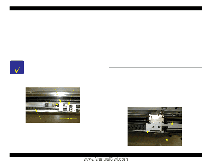
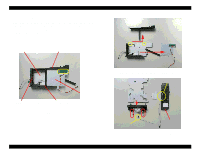
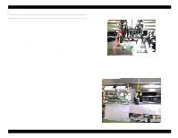
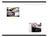
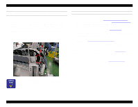
EPSON Stylus Pro 9000 CONNECTING THE INK TUBES TO THE INK PIPES 1. Make sure the ink tubes on the ink pipe side are uncovered for about 45 mm. 2. Make sure there is a screw and O-ring on the end of each ink tube. If some are missing, use ones from the old ink tubes. 3. Insert the inner clear tube into the corresponding color ink pipe as far as it will go. Repeat for all six tubes. 4. Secure the joint screws by hand temporally, and use the torque wrench (1.75Å}0.25kgf/cm) to fasten the screws completely. The ink tube must be inserted completely, and the O-ring must not be twisted. Make sure the end of the tube guide that attaches to the ink pipes has only FOUR joints. CR cable fixing plate CR fixing plate C (underneath) Tube guide fixing plate SECURING THE THE INK TUBES AND INK PIPES 1. Slide the UL tube adjuster (on the end of each tube) towards the joint screw side. 2. Place the CR fixing plate over the ink tubes and carefully but firmly press down until all three tubes are secure. Repeat for the other side. 3. Secure the tube guides and ink tubes with the CR cable fixing plates and tube guide fixing plate, then insert and close two screw(3Å~20) to secure the CR cable fixing plates. At this time, the tube guide sticks out about 6mm from the tube guide fixing plate. 4. Place the black tube fixing plate over the ink pipes (over the black pad), and press down to make sure all the pipes are secured by the plate. Secure the plate with a screw (3Å~16), and repear for the other side. SECURING THE TUBE GUIDES ON THE CR SIDE 1. Place both tube guides on the cable connection plate, aligning the ends of both tube guides with the far edges of the cable connection plate. 2. Put the right-side protective film on top of the cable connection plate and tube guide. Make sure the protective film is not too loose or too tight. 3. Put the new tube guide fixing plate on top of the tube guides and protective film, and secure all with three screws. 4. Make sure there is no gap between the protective film and the tube guide. Tube guide 6mm Disassembly & Assembly Protective film Tube guide fixing plater Align the edge of the tube guide here. 96
-
 1
1 -
2
-
3
-
4
-
5
-
6
-
7
-
8
-
9
-
10
-
11
-
12
-
13
-
14
-
15
-
16
-
17
-
18
-
19
-
20
-
21
-
22
-
23
-
24
-
25
-
26
-
27
-
28
-
29
-
30
-
31
-
32
-
33
-
34
-
35
-
36
-
37
-
38
-
39
-
40
-
41
-
42
-
43
-
44
-
45
-
46
-
47
-
48
-
49
-
50
-
51
-
52
-
53
-
54
-
55
-
56
-
57
-
58
-
59
-
60
-
61
-
62
-
63
-
64
-
65
-
66
-
67
-
68
-
69
-
70
-
71
-
72
-
73
-
74
-
75
-
76
-
77
-
78
-
79
-
80
-
81
-
82
-
83
-
84
-
85
-
86
-
87
-
88
-
89
-
90
-
 91
91 -
 92
92 -
 93
93 -
 94
94 -
 95
95 -
 96
96 -
 97
97 -
 98
98 -
 99
99 -
 100
100 -
 101
101 -
102
-
103
-
104
-
105
-
106
-
107
-
108
-
109
-
110
-
111
-
112
-
113
-
114
-
115
-
116
-
117
-
118
-
119
-
120
-
121
-
122
-
123
-
124
-
125
-
126
-
127
-
128
-
129
-
130
-
131
-
132
-
133
-
134
-
135
-
136
-
137
-
138
-
139
-
140
-
141
-
142
-
143
-
144
-
145
-
146
-
147
-
148
-
149
-
150
-
151
-
152
-
153
-
154
-
155
-
156
-
157
-
158
-
159
-
160
-
161
-
162
-
163
-
164
-
165
-
166
-
167
-
168
-
169
-
170
-
171
-
172
-
173
-
174
-
175
-
176
-
177
-
178
-
179
-
180
-
181
-
182
-
183
-
184
-
185
-
186
-
187
-
188
-
189
-
190
-
191
-
192
-
193
-
194
-
195
-
196
-
197
-
198
 |
 |