Epson Stylus Pro 9000 Service Manual - Page 61
Front Cover Removal
 |
View all Epson Stylus Pro 9000 manuals
Add to My Manuals
Save this manual to your list of manuals |
Page 61 highlights
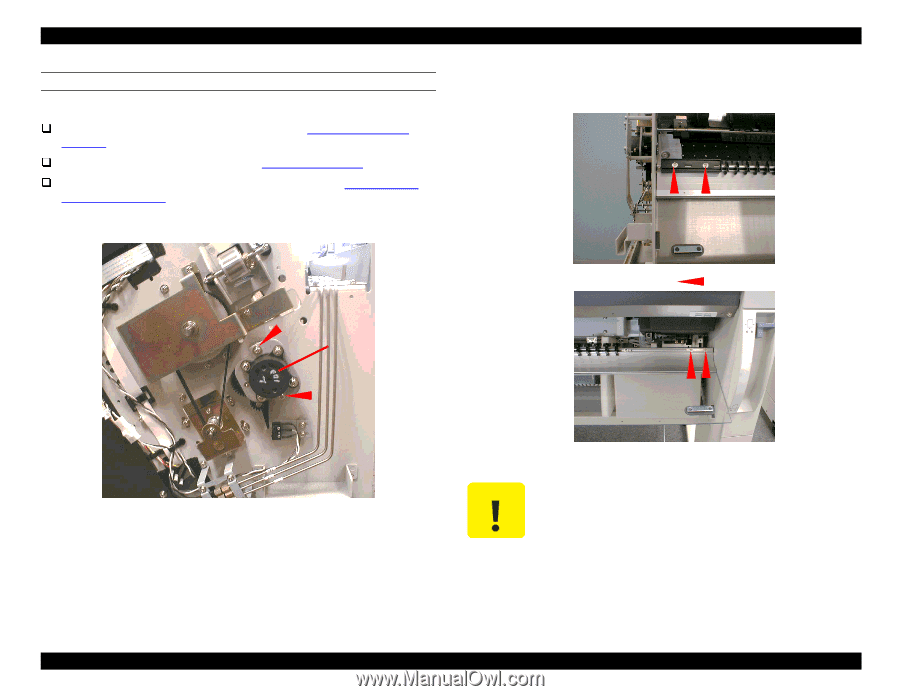
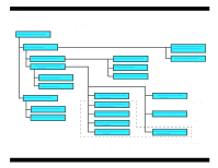
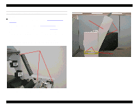
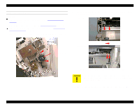
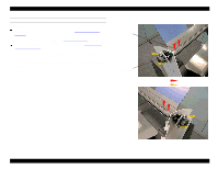
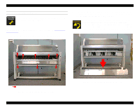
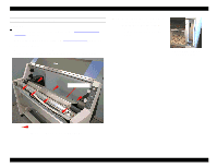
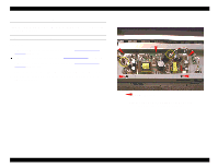
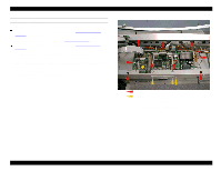
EPSON Stylus Pro 9000 FRONT COVER REMOVAL Preparation: Remove the Maintenance Cover as described in Maintenance Cover Removal on page 58. Remove the Top Cover as described in Top Cover Removal on page 59. Remove the Left and Right Side Covers as described in Left and Right Side Cover Removal on page 60. 1. Remove the two screws (CP(W2) M3x8) securing the damper assembly on the left side of the printer, and then remove the damper assembly. 2. The Front Cover Assembly hinges on a mounting pin at each end. Remove the four screws securing the mounting pins as shown below. Left side Right side CP(W2) M3x8 screws Damper Assembly Figure 4-8. Removing the Damper Assembly Disassembly & Assembly Figure 4-9. Locations of Front Cover Shaft Screws When removing the Front Cover, avoid tilting it down to the left. The little wheels mounted on the cover's shaft are not secured and may slide off. 3. While supporting the Front Cover, pull out the mounting pins, and then remove the Front Cover from the printer. 61
-
 1
1 -
2
-
3
-
4
-
5
-
6
-
7
-
8
-
9
-
10
-
11
-
12
-
13
-
14
-
15
-
16
-
17
-
18
-
19
-
20
-
21
-
22
-
23
-
24
-
25
-
26
-
27
-
28
-
29
-
30
-
31
-
32
-
33
-
34
-
35
-
36
-
37
-
38
-
39
-
40
-
41
-
42
-
43
-
44
-
45
-
46
-
47
-
48
-
49
-
50
-
51
-
52
-
53
-
54
-
55
-
 56
56 -
 57
57 -
 58
58 -
 59
59 -
 60
60 -
 61
61 -
 62
62 -
 63
63 -
 64
64 -
 65
65 -
 66
66 -
67
-
68
-
69
-
70
-
71
-
72
-
73
-
74
-
75
-
76
-
77
-
78
-
79
-
80
-
81
-
82
-
83
-
84
-
85
-
86
-
87
-
88
-
89
-
90
-
91
-
92
-
93
-
94
-
95
-
96
-
97
-
98
-
99
-
100
-
101
-
102
-
103
-
104
-
105
-
106
-
107
-
108
-
109
-
110
-
111
-
112
-
113
-
114
-
115
-
116
-
117
-
118
-
119
-
120
-
121
-
122
-
123
-
124
-
125
-
126
-
127
-
128
-
129
-
130
-
131
-
132
-
133
-
134
-
135
-
136
-
137
-
138
-
139
-
140
-
141
-
142
-
143
-
144
-
145
-
146
-
147
-
148
-
149
-
150
-
151
-
152
-
153
-
154
-
155
-
156
-
157
-
158
-
159
-
160
-
161
-
162
-
163
-
164
-
165
-
166
-
167
-
168
-
169
-
170
-
171
-
172
-
173
-
174
-
175
-
176
-
177
-
178
-
179
-
180
-
181
-
182
-
183
-
184
-
185
-
186
-
187
-
188
-
189
-
190
-
191
-
192
-
193
-
194
-
195
-
196
-
197
-
198
 |
 |