Epson Stylus Pro 9000 Service Manual - Page 24
Operation, 2.2.1 Carriage Mechanism, Carriage (CR) Guide Rail, Platen Gap (PG) Mechanism
 |
View all Epson Stylus Pro 9000 manuals
Add to My Manuals
Save this manual to your list of manuals |
Page 24 highlights
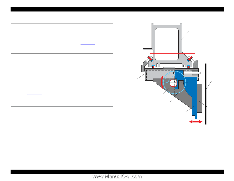
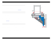
EPSON Stylus Pro 9000 2.2 Operation The following sections describe how the printer's main components operate. 2.2.1 Carriage Mechanism The carriage mechanism includes the parts shown in Figure 2-5. Their operation is described below. CARRIAGE (CR) GUIDE RAIL To print on paper as wide as B0, the printhead carriage must be more stable and must travel further than the usual carriage. To make the printheads more stable, EPSON added the CR Guide Rail to the Stylus Pro 9000. Every EPSON ink jet printer until now has used a carriage guide shaft to stabilize the carriage during printing and horizontal movement. The Stylus Pro 9000 does away with the carriage guide shaft and relies on the printer frame for its stability. As shown in Figure 2-5, the Carriage attaches to the CR Guide Rail with eight bearings, and the carriage in turn holds the subcarriage. The subcarriage holds the printheads. PLATEN GAP (PG) MECHANISM Unlike previous models, the Stylus Pro 9000 uses a special system to ensure that the distance between the printhead nozzles and paper remains the same for all supported paper thicknesses. The subcarriage can be moved using the PG Cam which is driven by the PG Gear; this causes the subcarriage and all its components to move slightly nearer to or farther from the platen. The subcarriage moves because the PG Cam is mounted off-center, so one side of the cam pushes the subcarriage closer to the platen than the other side. CR Guide Rail Bearings Carriage PG Cam PG Gear Subcarriage Platen Printhead Figure 2-5. CR Guide Rail and PG Mechanism (side view) Technical Overview 24
-
 1
1 -
2
-
3
-
4
-
5
-
6
-
7
-
8
-
9
-
10
-
11
-
12
-
13
-
14
-
15
-
16
-
17
-
18
-
 19
19 -
 20
20 -
 21
21 -
 22
22 -
 23
23 -
 24
24 -
 25
25 -
 26
26 -
 27
27 -
 28
28 -
 29
29 -
30
-
31
-
32
-
33
-
34
-
35
-
36
-
37
-
38
-
39
-
40
-
41
-
42
-
43
-
44
-
45
-
46
-
47
-
48
-
49
-
50
-
51
-
52
-
53
-
54
-
55
-
56
-
57
-
58
-
59
-
60
-
61
-
62
-
63
-
64
-
65
-
66
-
67
-
68
-
69
-
70
-
71
-
72
-
73
-
74
-
75
-
76
-
77
-
78
-
79
-
80
-
81
-
82
-
83
-
84
-
85
-
86
-
87
-
88
-
89
-
90
-
91
-
92
-
93
-
94
-
95
-
96
-
97
-
98
-
99
-
100
-
101
-
102
-
103
-
104
-
105
-
106
-
107
-
108
-
109
-
110
-
111
-
112
-
113
-
114
-
115
-
116
-
117
-
118
-
119
-
120
-
121
-
122
-
123
-
124
-
125
-
126
-
127
-
128
-
129
-
130
-
131
-
132
-
133
-
134
-
135
-
136
-
137
-
138
-
139
-
140
-
141
-
142
-
143
-
144
-
145
-
146
-
147
-
148
-
149
-
150
-
151
-
152
-
153
-
154
-
155
-
156
-
157
-
158
-
159
-
160
-
161
-
162
-
163
-
164
-
165
-
166
-
167
-
168
-
169
-
170
-
171
-
172
-
173
-
174
-
175
-
176
-
177
-
178
-
179
-
180
-
181
-
182
-
183
-
184
-
185
-
186
-
187
-
188
-
189
-
190
-
191
-
192
-
193
-
194
-
195
-
196
-
197
-
198
 |
 |