Epson Stylus Pro 9000 Service Manual - Page 71
Printer Mechanism Disassembly, Replacing the Printheads,
 |
View all Epson Stylus Pro 9000 manuals
Add to My Manuals
Save this manual to your list of manuals |
Page 71 highlights
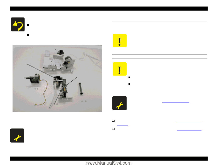
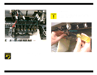
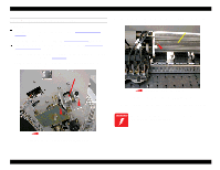
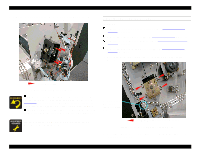
EPSON Stylus Pro 9000 If you re-install the same Capping Mechanism, be sure to check the following: After re-installing the springs that hold the Capping Mechanism in place, try sliding the mechanism by hand to make sure it operates smoothly. Make sure the air bleed valve seals properly when the Capping Mechanism pushes all the way against it. Flushing Box 4.5 Printer Mechanism Disassembly Follow the steps below to remove the main components of the printer mechanism. Do not attempt to disassemble any components other than those described below. Certain repairs can be done only at the factory and can permanently damage the printer if not done correctly. Pump Mechanism Carriage Lock Pump Motor Capping Mechanism Pump Drive Shaft Bleed Valve REPLACING THE PRINTHEADS The printer uses two printheads, Head B and Head C. Although they are similar, they are not interchangeable. One is for dark ink, the other for light ink. Make sure you install the correct replacement head accordingly: Head B (for dark ink; goes on the left) F055040: "Printhead, IJ192-OAD" Head C (for light ink; goes on the right) F055050: "Printhead, IJ192- OAE" When replacing the printheads, you have to perform various adjustments. See Required Adjustments on page 103. Figure 4-23. Disassembling the Maintenance Assembly - 2 When replacing the Lower Paper Guide, you need to perform the Cutter Position Adjustment. Preparation: Remove the Maintenance Cover as described in Maintenance Cover Removal on page 58. Optional: Remove the Top Cover as described in Top Cover Removal on page 59. Although this is an extra step, it provides more light and room. Disassembly & Assembly 71
-
 1
1 -
2
-
3
-
4
-
5
-
6
-
7
-
8
-
9
-
10
-
11
-
12
-
13
-
14
-
15
-
16
-
17
-
18
-
19
-
20
-
21
-
22
-
23
-
24
-
25
-
26
-
27
-
28
-
29
-
30
-
31
-
32
-
33
-
34
-
35
-
36
-
37
-
38
-
39
-
40
-
41
-
42
-
43
-
44
-
45
-
46
-
47
-
48
-
49
-
50
-
51
-
52
-
53
-
54
-
55
-
56
-
57
-
58
-
59
-
60
-
61
-
62
-
63
-
64
-
65
-
 66
66 -
 67
67 -
 68
68 -
 69
69 -
 70
70 -
 71
71 -
 72
72 -
 73
73 -
 74
74 -
 75
75 -
 76
76 -
77
-
78
-
79
-
80
-
81
-
82
-
83
-
84
-
85
-
86
-
87
-
88
-
89
-
90
-
91
-
92
-
93
-
94
-
95
-
96
-
97
-
98
-
99
-
100
-
101
-
102
-
103
-
104
-
105
-
106
-
107
-
108
-
109
-
110
-
111
-
112
-
113
-
114
-
115
-
116
-
117
-
118
-
119
-
120
-
121
-
122
-
123
-
124
-
125
-
126
-
127
-
128
-
129
-
130
-
131
-
132
-
133
-
134
-
135
-
136
-
137
-
138
-
139
-
140
-
141
-
142
-
143
-
144
-
145
-
146
-
147
-
148
-
149
-
150
-
151
-
152
-
153
-
154
-
155
-
156
-
157
-
158
-
159
-
160
-
161
-
162
-
163
-
164
-
165
-
166
-
167
-
168
-
169
-
170
-
171
-
172
-
173
-
174
-
175
-
176
-
177
-
178
-
179
-
180
-
181
-
182
-
183
-
184
-
185
-
186
-
187
-
188
-
189
-
190
-
191
-
192
-
193
-
194
-
195
-
196
-
197
-
198
 |
 |