Epson Stylus Pro 9000 Service Manual - Page 136
Sensor Trimmer Adjustment
 |
View all Epson Stylus Pro 9000 manuals
Add to My Manuals
Save this manual to your list of manuals |
Page 136 highlights
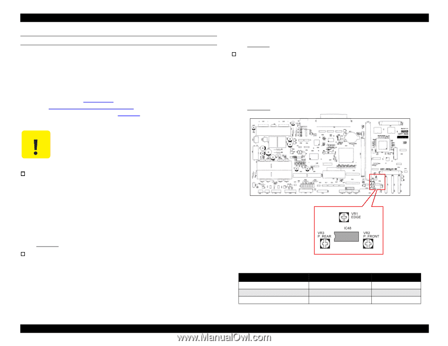
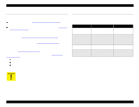
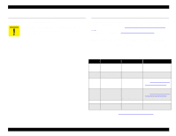
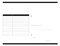
EPSON Stylus Pro 9000 SENSOR TRIMMER ADJUSTMENT After replacing the C277MAIN board, you need to adjust the sensitivity of three sensors: Paper Edge Sensor, Front Paper Sensor, and Rear Paper Sensor. You also need to perform this adjustment if you replace one or more of these sensors (perform the adjustment only for the sensors that you replace). To perform the adjustment, you need to access variable resistors VR1-VR3 on the Main Board (see the figure at right). Remove the access plate on top of the Upper Paper Guide (see Figure 4-13 on page 64). Enter the Self-Diagnostic Mode (see Using the Self-Diagnostic Mode on page 108), select "Test Menu," and then select "Sensors" (see Sensors on page 112). Then follow the instructions below for each sensor that you need to adjust. When making this adjustments, avoid strong light (such as sunlight) near the printer. These sensors are photo-sensitive and do not function properly under strong lighting. Paper Edge Sensor 1. Move the carriage left and right manually and make sure that the signal level indicated on the LCD is smaller than 18H (hexadecimal value). 2. Place a sheet of coated ink jet paper in the paper path, and lower the Paper Release Lever to lock the paper in position. 3. Move the carriage over the paper so that the Paper Edge Sensor is located in the middle of the paper. 4. Adjust VR1 on the Main Board so that the signal level indicated on the LCD is 80H ±8H (between 78 and 88, hex). Front Paper Sensor 1. As above, make sure that the signal level indicated on the LCD is smaller than 18H. 2. Place a sheet of coated ink jet paper in front of the Front Paper Sensor located on the Lower Paper Guide; lower the Paper Release Lever to lock the paper in position. 3. Adjust VR2 on the Main Board so that the signal level indicated on the LCD is 87H ±8H (between 7F and 8F, hex). Rear Paper Sensor 1. As above, make sure that the signal level indicated on the LCD is smaller than 18H. 2. Place a sheet of coated ink jet paper over the Rear Paper Sensor located in the Upper Paper Guide, and hold it in place or secure it with tape. 3. Adjust VR3 on the Main Board so that the signal level indicated on the LCD is 8AH ±8H (between 82 and 92, hex). Table 5-14. Sensor Adjustment Values Sensor Without Paper With Paper Paper Edge Sensor Front Paper Sensor Rear Paper Sensor 18H or less 18H or less 18H or less 80H ±8H 87H ±8H 8AH ±8H Adjustments 136
-
 1
1 -
2
-
3
-
4
-
5
-
6
-
7
-
8
-
9
-
10
-
11
-
12
-
13
-
14
-
15
-
16
-
17
-
18
-
19
-
20
-
21
-
22
-
23
-
24
-
25
-
26
-
27
-
28
-
29
-
30
-
31
-
32
-
33
-
34
-
35
-
36
-
37
-
38
-
39
-
40
-
41
-
42
-
43
-
44
-
45
-
46
-
47
-
48
-
49
-
50
-
51
-
52
-
53
-
54
-
55
-
56
-
57
-
58
-
59
-
60
-
61
-
62
-
63
-
64
-
65
-
66
-
67
-
68
-
69
-
70
-
71
-
72
-
73
-
74
-
75
-
76
-
77
-
78
-
79
-
80
-
81
-
82
-
83
-
84
-
85
-
86
-
87
-
88
-
89
-
90
-
91
-
92
-
93
-
94
-
95
-
96
-
97
-
98
-
99
-
100
-
101
-
102
-
103
-
104
-
105
-
106
-
107
-
108
-
109
-
110
-
111
-
112
-
113
-
114
-
115
-
116
-
117
-
118
-
119
-
120
-
121
-
122
-
123
-
124
-
125
-
126
-
127
-
128
-
129
-
130
-
 131
131 -
 132
132 -
 133
133 -
 134
134 -
 135
135 -
 136
136 -
 137
137 -
 138
138 -
 139
139 -
 140
140 -
 141
141 -
142
-
143
-
144
-
145
-
146
-
147
-
148
-
149
-
150
-
151
-
152
-
153
-
154
-
155
-
156
-
157
-
158
-
159
-
160
-
161
-
162
-
163
-
164
-
165
-
166
-
167
-
168
-
169
-
170
-
171
-
172
-
173
-
174
-
175
-
176
-
177
-
178
-
179
-
180
-
181
-
182
-
183
-
184
-
185
-
186
-
187
-
188
-
189
-
190
-
191
-
192
-
193
-
194
-
195
-
196
-
197
-
198
 |
 |