Epson Stylus Pro 9000 Service Manual - Page 74
Printhead Tension Spring and Screw Removal, K, C, M, LC, LM, Y.
 |
View all Epson Stylus Pro 9000 manuals
Add to My Manuals
Save this manual to your list of manuals |
Page 74 highlights
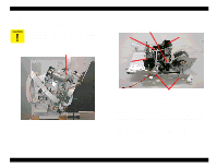
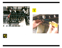
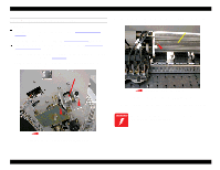
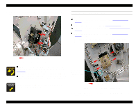
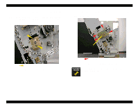
EPSON Stylus Pro 9000 7. Using needle-nosed pliers, remove the Tension Spring. 10. Repeat steps 10 and 11 for the other printhead if necessary. When replacing the printheads, fold the flat cable behind the printhead and make sure the printhead snaps fully into place. When properly installed, the printhead ID is directly behind and at the same height as the PG Cam Shaft. If the PG Cam Shaft does not partially block the line of sight of the printhead ID (when looking at the ID from straight in front), the printhead is not installed properly. When attaching the dampers to the printhead, follow the same order, left to right, as shown on the control panel: K, C, M, LC, LM, Y. Tension Spring CB M3x6 Figure 4-28. Printhead Tension Spring and Screw Removal 8. Remove the CB M3x6 screw, and then remove the printhead from the carriage. 9. Remove the flat cable from the back of the printhead. Disassembly & Assembly 74
-
 1
1 -
2
-
3
-
4
-
5
-
6
-
7
-
8
-
9
-
10
-
11
-
12
-
13
-
14
-
15
-
16
-
17
-
18
-
19
-
20
-
21
-
22
-
23
-
24
-
25
-
26
-
27
-
28
-
29
-
30
-
31
-
32
-
33
-
34
-
35
-
36
-
37
-
38
-
39
-
40
-
41
-
42
-
43
-
44
-
45
-
46
-
47
-
48
-
49
-
50
-
51
-
52
-
53
-
54
-
55
-
56
-
57
-
58
-
59
-
60
-
61
-
62
-
63
-
64
-
65
-
66
-
67
-
68
-
 69
69 -
 70
70 -
 71
71 -
 72
72 -
 73
73 -
 74
74 -
 75
75 -
 76
76 -
 77
77 -
 78
78 -
 79
79 -
80
-
81
-
82
-
83
-
84
-
85
-
86
-
87
-
88
-
89
-
90
-
91
-
92
-
93
-
94
-
95
-
96
-
97
-
98
-
99
-
100
-
101
-
102
-
103
-
104
-
105
-
106
-
107
-
108
-
109
-
110
-
111
-
112
-
113
-
114
-
115
-
116
-
117
-
118
-
119
-
120
-
121
-
122
-
123
-
124
-
125
-
126
-
127
-
128
-
129
-
130
-
131
-
132
-
133
-
134
-
135
-
136
-
137
-
138
-
139
-
140
-
141
-
142
-
143
-
144
-
145
-
146
-
147
-
148
-
149
-
150
-
151
-
152
-
153
-
154
-
155
-
156
-
157
-
158
-
159
-
160
-
161
-
162
-
163
-
164
-
165
-
166
-
167
-
168
-
169
-
170
-
171
-
172
-
173
-
174
-
175
-
176
-
177
-
178
-
179
-
180
-
181
-
182
-
183
-
184
-
185
-
186
-
187
-
188
-
189
-
190
-
191
-
192
-
193
-
194
-
195
-
196
-
197
-
198
 |
 |
