Epson Stylus Pro 9000 Service Manual - Page 60
Left and Right Side Cover Removal
 |
View all Epson Stylus Pro 9000 manuals
Add to My Manuals
Save this manual to your list of manuals |
Page 60 highlights
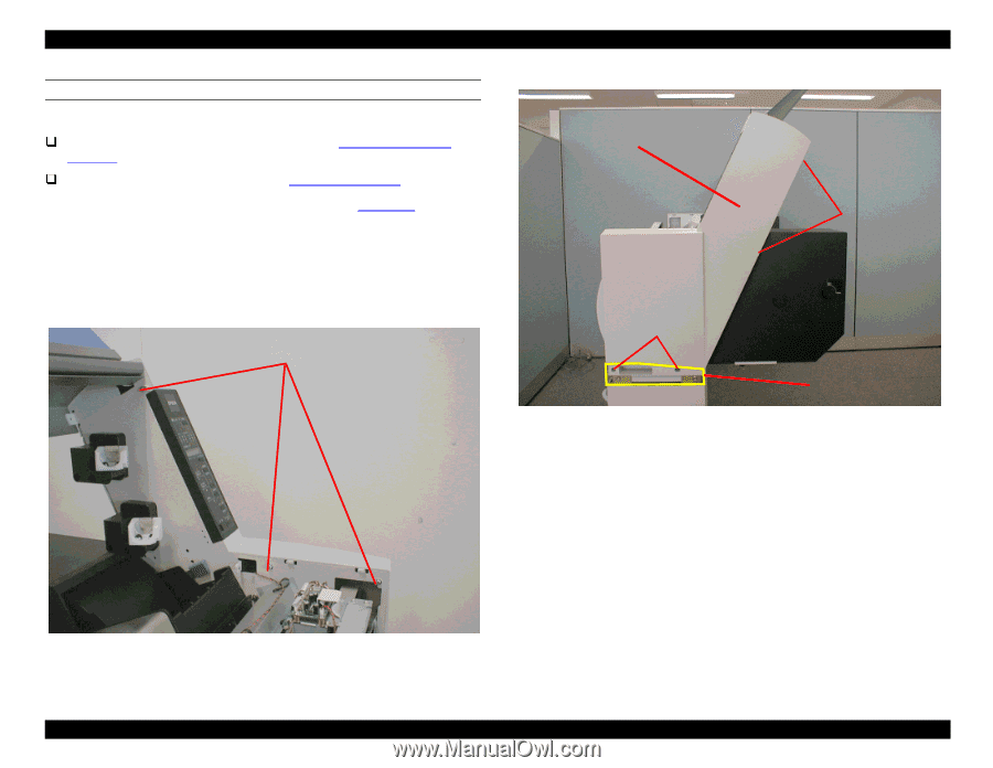
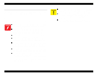
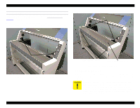
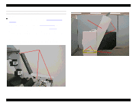
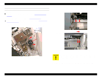
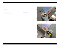
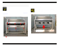
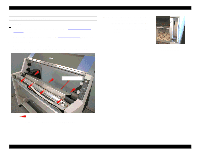
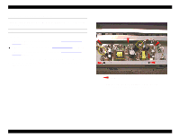
EPSON Stylus Pro 9000 LEFT AND RIGHT SIDE COVER REMOVAL Preparation: Remove the Maintenance Cover as described in Maintenance Cover Removal on page 58. Remove the Top Cover as described in Top Cover Removal on page 59. 1. Remove the left and right Joint Covers, as shown in Figure 4-7. 2. Remove the seven screws (five silver CP(W2) M4x12 and two black CP(W2) M4x12) securing the Left Side Cover, and remove the Left Side Cover. Repeat for the Right Side Cover. NOTE: The control panel is attached to the Right Side Cover. When removing the Right Side Cover, detach the flat cable from the control panel. CP (W2) M4x12 silver screws Right Side Cover CP (W2) M4x12 silver screws CP (W2) M4x12 black screws Joint Cover Figure 4-7. L/R Side Cover Outer Screw Location Figure 4-6. L/R Side Cover Inner Screw Location Disassembly & Assembly 60
-
 1
1 -
2
-
3
-
4
-
5
-
6
-
7
-
8
-
9
-
10
-
11
-
12
-
13
-
14
-
15
-
16
-
17
-
18
-
19
-
20
-
21
-
22
-
23
-
24
-
25
-
26
-
27
-
28
-
29
-
30
-
31
-
32
-
33
-
34
-
35
-
36
-
37
-
38
-
39
-
40
-
41
-
42
-
43
-
44
-
45
-
46
-
47
-
48
-
49
-
50
-
51
-
52
-
53
-
54
-
 55
55 -
 56
56 -
 57
57 -
 58
58 -
 59
59 -
 60
60 -
 61
61 -
 62
62 -
 63
63 -
 64
64 -
 65
65 -
66
-
67
-
68
-
69
-
70
-
71
-
72
-
73
-
74
-
75
-
76
-
77
-
78
-
79
-
80
-
81
-
82
-
83
-
84
-
85
-
86
-
87
-
88
-
89
-
90
-
91
-
92
-
93
-
94
-
95
-
96
-
97
-
98
-
99
-
100
-
101
-
102
-
103
-
104
-
105
-
106
-
107
-
108
-
109
-
110
-
111
-
112
-
113
-
114
-
115
-
116
-
117
-
118
-
119
-
120
-
121
-
122
-
123
-
124
-
125
-
126
-
127
-
128
-
129
-
130
-
131
-
132
-
133
-
134
-
135
-
136
-
137
-
138
-
139
-
140
-
141
-
142
-
143
-
144
-
145
-
146
-
147
-
148
-
149
-
150
-
151
-
152
-
153
-
154
-
155
-
156
-
157
-
158
-
159
-
160
-
161
-
162
-
163
-
164
-
165
-
166
-
167
-
168
-
169
-
170
-
171
-
172
-
173
-
174
-
175
-
176
-
177
-
178
-
179
-
180
-
181
-
182
-
183
-
184
-
185
-
186
-
187
-
188
-
189
-
190
-
191
-
192
-
193
-
194
-
195
-
196
-
197
-
198
 |
 |