Epson Stylus Pro 9000 Service Manual - Page 83
Removing the Carriage HP Sensor and Encoder Sensor, Carriage HP Sensor, Encoder Sensor
 |
View all Epson Stylus Pro 9000 manuals
Add to My Manuals
Save this manual to your list of manuals |
Page 83 highlights
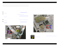
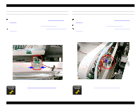
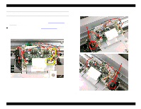
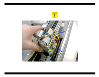
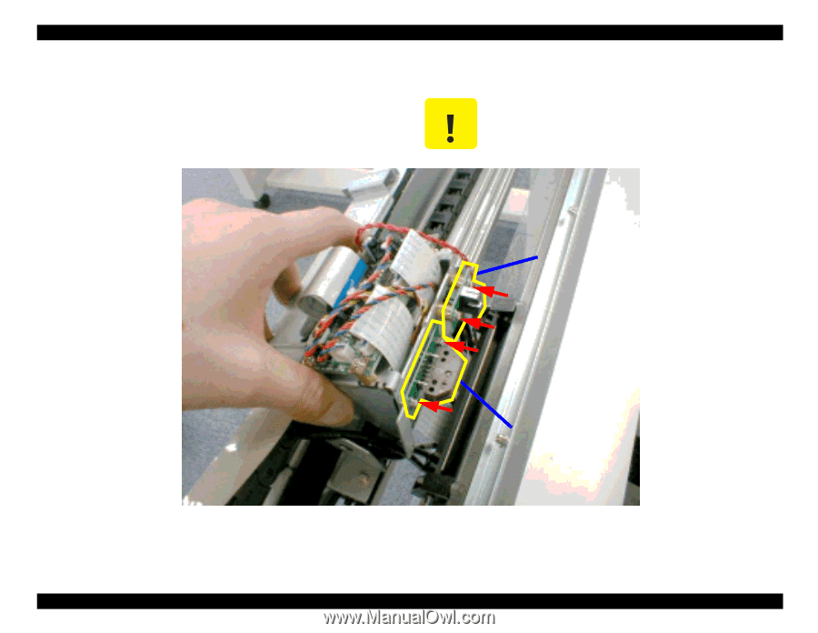
EPSON Stylus Pro 9000 3. Separate the circuit board and its mounting frame from the carriage assembly by lifting them up as shown below. 4. Remove the two screws (CP(W2) M3x6) securing each sensor to the back of the circuit board mounting frame, and remove the sensors. Avoid scratching the timing fence when removing the Encoder. Carriage HP Sensor Encoder Sensor Figure 4-45. Removing the Carriage HP Sensor and Encoder Sensor Disassembly & Assembly 83
-
 1
1 -
2
-
3
-
4
-
5
-
6
-
7
-
8
-
9
-
10
-
11
-
12
-
13
-
14
-
15
-
16
-
17
-
18
-
19
-
20
-
21
-
22
-
23
-
24
-
25
-
26
-
27
-
28
-
29
-
30
-
31
-
32
-
33
-
34
-
35
-
36
-
37
-
38
-
39
-
40
-
41
-
42
-
43
-
44
-
45
-
46
-
47
-
48
-
49
-
50
-
51
-
52
-
53
-
54
-
55
-
56
-
57
-
58
-
59
-
60
-
61
-
62
-
63
-
64
-
65
-
66
-
67
-
68
-
69
-
70
-
71
-
72
-
73
-
74
-
75
-
76
-
77
-
 78
78 -
 79
79 -
 80
80 -
 81
81 -
 82
82 -
 83
83 -
 84
84 -
 85
85 -
 86
86 -
 87
87 -
 88
88 -
89
-
90
-
91
-
92
-
93
-
94
-
95
-
96
-
97
-
98
-
99
-
100
-
101
-
102
-
103
-
104
-
105
-
106
-
107
-
108
-
109
-
110
-
111
-
112
-
113
-
114
-
115
-
116
-
117
-
118
-
119
-
120
-
121
-
122
-
123
-
124
-
125
-
126
-
127
-
128
-
129
-
130
-
131
-
132
-
133
-
134
-
135
-
136
-
137
-
138
-
139
-
140
-
141
-
142
-
143
-
144
-
145
-
146
-
147
-
148
-
149
-
150
-
151
-
152
-
153
-
154
-
155
-
156
-
157
-
158
-
159
-
160
-
161
-
162
-
163
-
164
-
165
-
166
-
167
-
168
-
169
-
170
-
171
-
172
-
173
-
174
-
175
-
176
-
177
-
178
-
179
-
180
-
181
-
182
-
183
-
184
-
185
-
186
-
187
-
188
-
189
-
190
-
191
-
192
-
193
-
194
-
195
-
196
-
197
-
198
 |
 |
EPSON Stylus Pro 9000
Disassembly & Assembly
83
3.
Separate the circuit board and its mounting frame from the carriage
assembly by lifting them up as shown below.
4.
Remove the two screws (CP(W2) M3x6) securing each sensor to the back
of the circuit board mounting frame, and remove the sensors.
Figure 4-45.
Removing the Carriage HP Sensor and Encoder Sensor
C
A
U
T
I
O
N
Avoid scratching the timing fence when removing the
Encoder.
Carriage HP Sensor
Encoder Sensor