Epson Stylus Pro 9000 Service Manual - Page 82
Removing the Carriage Home Position Sensor and Encoder, Maintenance Cover, Removal, Top Cover Removal
 |
View all Epson Stylus Pro 9000 manuals
Add to My Manuals
Save this manual to your list of manuals |
Page 82 highlights
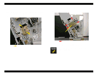
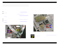
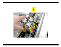
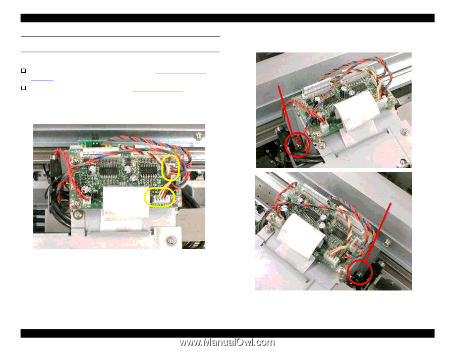
EPSON Stylus Pro 9000 REMOVING THE CARRIAGE HOME POSITION SENSOR AND ENCODER Preparation: Remove the Maintenance Cover as described in Maintenance Cover Removal on page 58. Remove the Top Cover as described in Top Cover Removal on page 59. 1. Disconnect the cables from CN2 (Encoder) and CN4 (HP Sensor) on the carriage circuit board. 2. Remove the two screws (CP(W2) M3x6) securing the circuit board mounting frame to the carriage assembly. Screw Figure 4-43. Disconnecting the Cables Disassembly & Assembly Screw Figure 4-44. Removing the Circuit Board Mounting Frame Screws 82
-
 1
1 -
2
-
3
-
4
-
5
-
6
-
7
-
8
-
9
-
10
-
11
-
12
-
13
-
14
-
15
-
16
-
17
-
18
-
19
-
20
-
21
-
22
-
23
-
24
-
25
-
26
-
27
-
28
-
29
-
30
-
31
-
32
-
33
-
34
-
35
-
36
-
37
-
38
-
39
-
40
-
41
-
42
-
43
-
44
-
45
-
46
-
47
-
48
-
49
-
50
-
51
-
52
-
53
-
54
-
55
-
56
-
57
-
58
-
59
-
60
-
61
-
62
-
63
-
64
-
65
-
66
-
67
-
68
-
69
-
70
-
71
-
72
-
73
-
74
-
75
-
76
-
 77
77 -
 78
78 -
 79
79 -
 80
80 -
 81
81 -
 82
82 -
 83
83 -
 84
84 -
 85
85 -
 86
86 -
 87
87 -
88
-
89
-
90
-
91
-
92
-
93
-
94
-
95
-
96
-
97
-
98
-
99
-
100
-
101
-
102
-
103
-
104
-
105
-
106
-
107
-
108
-
109
-
110
-
111
-
112
-
113
-
114
-
115
-
116
-
117
-
118
-
119
-
120
-
121
-
122
-
123
-
124
-
125
-
126
-
127
-
128
-
129
-
130
-
131
-
132
-
133
-
134
-
135
-
136
-
137
-
138
-
139
-
140
-
141
-
142
-
143
-
144
-
145
-
146
-
147
-
148
-
149
-
150
-
151
-
152
-
153
-
154
-
155
-
156
-
157
-
158
-
159
-
160
-
161
-
162
-
163
-
164
-
165
-
166
-
167
-
168
-
169
-
170
-
171
-
172
-
173
-
174
-
175
-
176
-
177
-
178
-
179
-
180
-
181
-
182
-
183
-
184
-
185
-
186
-
187
-
188
-
189
-
190
-
191
-
192
-
193
-
194
-
195
-
196
-
197
-
198
 |
 |
EPSON Stylus Pro 9000
Disassembly & Assembly
82
REMOVING THE CARRIAGE HOME POSITION SENSOR AND
ENCODER
Preparation:
Remove the Maintenance Cover as described in
Maintenance Cover
Removal
on page 58.
Remove the Top Cover as described in
Top Cover Removal
on page 59.
1.
Disconnect the cables from CN2 (Encoder) and CN4 (HP Sensor) on the
carriage circuit board.
Figure 4-43.
Disconnecting the Cables
2.
Remove the two screws (CP(W2) M3x6) securing the circuit board
mounting frame to the carriage assembly.
Figure 4-44.
Removing the Circuit Board Mounting Frame Screws
Screw
Screw