Epson Stylus Pro 9000 Service Manual - Page 67
Maintenance Procedures, Replacing the Waste Ink Pads, Waste Ink Box Locations
 |
View all Epson Stylus Pro 9000 manuals
Add to My Manuals
Save this manual to your list of manuals |
Page 67 highlights
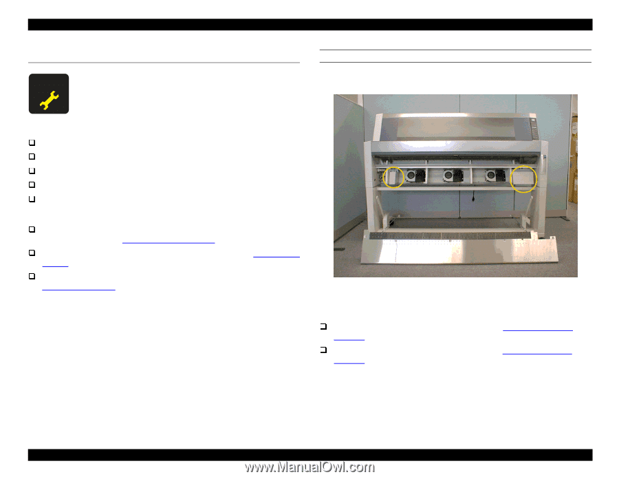
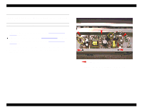
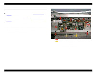
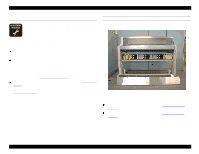
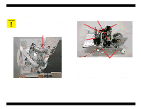
EPSON Stylus Pro 9000 4.4 Maintenance Procedures To keep the printhead clean and maintain print quality, the printer periodically flushes ink through the printhead, and the flushed ink drains into one of two Waste Ink Boxes. Once a predetermined amount of ink has drained into the Waste Ink Boxes, the printer displays the service call error-"00000100." When the service call error occurs, you need to replace the following parts: the Waste Ink Pads in the left and right Waste Ink Boxes the Flushing Boxes (right and left) the Pump Assembly the Capping Assembly the Head Cleaner Blade In addition to replacing these parts, you also need to do the following: perform the Cutter Position Adjustment after reinstalling the Lower Paper Guide, as described in Cutter Position Adjustment on page 131 reset the waste ink counter ("Init. Waste Ink") as described in Maintenance Mode 2 on page 17 reset the cleaning unit counter ("Init. Cleaning Unit") as described in Maintenance Mode 2 on page 17 Refer to the steps below to replace the Waste Ink Pads and other parts that are mounted on the Maintenance Assembly. REPLACING THE WASTE INK PADS Refer to the figure below to locate the left and right Waste Ink Boxes: Left Waste Ink Box Right Waste Ink Box Figure 4-17. Waste Ink Box Locations Preparation: Remove the Maintenance Cover as described in Maintenance Cover Removal on page 58. Remove the Lower Paper Guide as described in Lower Paper Guide Removal on page 63. Disassembly & Assembly 67
-
 1
1 -
2
-
3
-
4
-
5
-
6
-
7
-
8
-
9
-
10
-
11
-
12
-
13
-
14
-
15
-
16
-
17
-
18
-
19
-
20
-
21
-
22
-
23
-
24
-
25
-
26
-
27
-
28
-
29
-
30
-
31
-
32
-
33
-
34
-
35
-
36
-
37
-
38
-
39
-
40
-
41
-
42
-
43
-
44
-
45
-
46
-
47
-
48
-
49
-
50
-
51
-
52
-
53
-
54
-
55
-
56
-
57
-
58
-
59
-
60
-
61
-
 62
62 -
 63
63 -
 64
64 -
 65
65 -
 66
66 -
 67
67 -
 68
68 -
 69
69 -
 70
70 -
 71
71 -
 72
72 -
73
-
74
-
75
-
76
-
77
-
78
-
79
-
80
-
81
-
82
-
83
-
84
-
85
-
86
-
87
-
88
-
89
-
90
-
91
-
92
-
93
-
94
-
95
-
96
-
97
-
98
-
99
-
100
-
101
-
102
-
103
-
104
-
105
-
106
-
107
-
108
-
109
-
110
-
111
-
112
-
113
-
114
-
115
-
116
-
117
-
118
-
119
-
120
-
121
-
122
-
123
-
124
-
125
-
126
-
127
-
128
-
129
-
130
-
131
-
132
-
133
-
134
-
135
-
136
-
137
-
138
-
139
-
140
-
141
-
142
-
143
-
144
-
145
-
146
-
147
-
148
-
149
-
150
-
151
-
152
-
153
-
154
-
155
-
156
-
157
-
158
-
159
-
160
-
161
-
162
-
163
-
164
-
165
-
166
-
167
-
168
-
169
-
170
-
171
-
172
-
173
-
174
-
175
-
176
-
177
-
178
-
179
-
180
-
181
-
182
-
183
-
184
-
185
-
186
-
187
-
188
-
189
-
190
-
191
-
192
-
193
-
194
-
195
-
196
-
197
-
198
 |
 |