Epson Stylus Pro 9000 Service Manual - Page 98
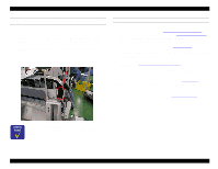
Connecting the ink tubes and dampers, should be covered completely.
 |
View all Epson Stylus Pro 9000 manuals
Add to My Manuals
Save this manual to your list of manuals |
Page 98 highlights
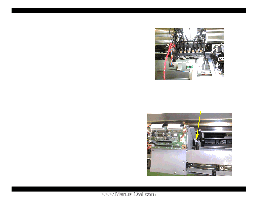
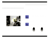
EPSON Stylus Pro 9000 CONNECTING THE INK TUBES AND DAMPERS 1. Return the carriage to the home position. 2. Arrange the dark series ink tubes from the tube guide to the dampers. The ink tubes should pass through the slot on the left side of the cable connection plate. Be sure not to twist the three tubes. 3. Make sure the tubes all have screws and O-rings on the ends. 4. Take one ink tube and apply cleaning liquid to the O-ring. 5. Insert the ink tube into the corresponding color damper as far as it will go, and close the screw by hand for now. 6. Make sure the ink tube is not twisted or bent and the O-ring is not twisted. Use the torque wrench (1.75Å}0.25kgf•cm) to tighten the screw completely. 7. Slide down the UL tube adjuster to the screw, and press down the tube to make sure it is fully inserted into the screw and damper. The ink tube should be covered completely. 8. Repeat steps four through seven for all dark color ink tubes. 9. Shift the carriage all the way to the left. 10. Arrange the dark series ink tubes from the tube guide to the dampers. The ink tubes should pass through the slot on the right side of the cable connection plate. Be sure not to twist the three tubes. 11. Connect the light color ink tubes as described in steps 3 through 8, substituting light for dark. The order of the ink tubes is shown on the control panel. 12. Secure the light-colored ink tubes to the cable connection plate with the plastic insulation lock (KI-100M). Insulation lock (KI-100M) Disassembly & Assembly 98
-
 1
1 -
2
-
3
-
4
-
5
-
6
-
7
-
8
-
9
-
10
-
11
-
12
-
13
-
14
-
15
-
16
-
17
-
18
-
19
-
20
-
21
-
22
-
23
-
24
-
25
-
26
-
27
-
28
-
29
-
30
-
31
-
32
-
33
-
34
-
35
-
36
-
37
-
38
-
39
-
40
-
41
-
42
-
43
-
44
-
45
-
46
-
47
-
48
-
49
-
50
-
51
-
52
-
53
-
54
-
55
-
56
-
57
-
58
-
59
-
60
-
61
-
62
-
63
-
64
-
65
-
66
-
67
-
68
-
69
-
70
-
71
-
72
-
73
-
74
-
75
-
76
-
77
-
78
-
79
-
80
-
81
-
82
-
83
-
84
-
85
-
86
-
87
-
88
-
89
-
90
-
91
-
92
-
 93
93 -
 94
94 -
 95
95 -
 96
96 -
 97
97 -
 98
98 -
 99
99 -
 100
100 -
 101
101 -
 102
102 -
 103
103 -
104
-
105
-
106
-
107
-
108
-
109
-
110
-
111
-
112
-
113
-
114
-
115
-
116
-
117
-
118
-
119
-
120
-
121
-
122
-
123
-
124
-
125
-
126
-
127
-
128
-
129
-
130
-
131
-
132
-
133
-
134
-
135
-
136
-
137
-
138
-
139
-
140
-
141
-
142
-
143
-
144
-
145
-
146
-
147
-
148
-
149
-
150
-
151
-
152
-
153
-
154
-
155
-
156
-
157
-
158
-
159
-
160
-
161
-
162
-
163
-
164
-
165
-
166
-
167
-
168
-
169
-
170
-
171
-
172
-
173
-
174
-
175
-
176
-
177
-
178
-
179
-
180
-
181
-
182
-
183
-
184
-
185
-
186
-
187
-
188
-
189
-
190
-
191
-
192
-
193
-
194
-
195
-
196
-
197
-
198
 |
 |