Epson Stylus Pro 9000 Service Manual - Page 81
Removing the Front Paper Sensor, Removing the Paper Release Sensor, Maintenance Cover, Removal
 |
View all Epson Stylus Pro 9000 manuals
Add to My Manuals
Save this manual to your list of manuals |
Page 81 highlights
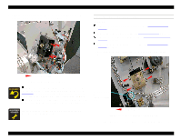
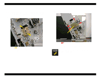
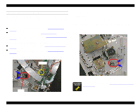
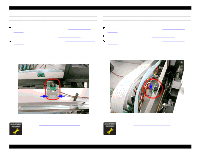
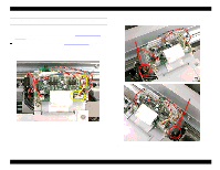
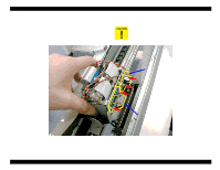
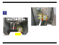
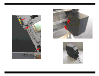
EPSON Stylus Pro 9000 REMOVING THE FRONT PAPER SENSOR Preparation: Remove the Maintenance Cover as described in Maintenance Cover Removal on page 58. Remove the Lower Paper Guide as described in Lower Paper Guide Removal on page 63. 1. Disconnect the cable from CN11 on the relay board. 2. Remove the screw (CP(W) M3x6) securing the Front Paper Sensor, and remove the sensor. REMOVING THE PAPER RELEASE SENSOR The Paper Release Sensor detects the position of the Paper Release Lever. Preparation: Remove the Maintenance Cover as described in Maintenance Cover Removal on page 58. Remove the Top Cover as described in Top Cover Removal on page 59. Remove the Right Side Cover as described in Left and Right Side Cover Removal on page 60. 1. Disconnect the cable from CN10 on the relay board. 2. Remove the two screws (CP(W) M3x6) securing the Paper Release Sensor, and remove the sensor. One screw (behind the sensor board) Figure 4-41. Front Paper Sensor Removal After reinstalling the Lower Paper Guide, you need to perform the Cutter Position Adjustment on page 131. Disassembly & Assembly Paper Release Sensor Figure 4-42. Paper Release Sensor Removal 81
-
 1
1 -
2
-
3
-
4
-
5
-
6
-
7
-
8
-
9
-
10
-
11
-
12
-
13
-
14
-
15
-
16
-
17
-
18
-
19
-
20
-
21
-
22
-
23
-
24
-
25
-
26
-
27
-
28
-
29
-
30
-
31
-
32
-
33
-
34
-
35
-
36
-
37
-
38
-
39
-
40
-
41
-
42
-
43
-
44
-
45
-
46
-
47
-
48
-
49
-
50
-
51
-
52
-
53
-
54
-
55
-
56
-
57
-
58
-
59
-
60
-
61
-
62
-
63
-
64
-
65
-
66
-
67
-
68
-
69
-
70
-
71
-
72
-
73
-
74
-
75
-
 76
76 -
 77
77 -
 78
78 -
 79
79 -
 80
80 -
 81
81 -
 82
82 -
 83
83 -
 84
84 -
 85
85 -
 86
86 -
87
-
88
-
89
-
90
-
91
-
92
-
93
-
94
-
95
-
96
-
97
-
98
-
99
-
100
-
101
-
102
-
103
-
104
-
105
-
106
-
107
-
108
-
109
-
110
-
111
-
112
-
113
-
114
-
115
-
116
-
117
-
118
-
119
-
120
-
121
-
122
-
123
-
124
-
125
-
126
-
127
-
128
-
129
-
130
-
131
-
132
-
133
-
134
-
135
-
136
-
137
-
138
-
139
-
140
-
141
-
142
-
143
-
144
-
145
-
146
-
147
-
148
-
149
-
150
-
151
-
152
-
153
-
154
-
155
-
156
-
157
-
158
-
159
-
160
-
161
-
162
-
163
-
164
-
165
-
166
-
167
-
168
-
169
-
170
-
171
-
172
-
173
-
174
-
175
-
176
-
177
-
178
-
179
-
180
-
181
-
182
-
183
-
184
-
185
-
186
-
187
-
188
-
189
-
190
-
191
-
192
-
193
-
194
-
195
-
196
-
197
-
198
 |
 |
