Epson Stylus Pro 9000 Service Manual - Page 97
Checking the ink tubes, Attaching the CR circuit board, Connecting the carriage FFCs, Wrong
 |
View all Epson Stylus Pro 9000 manuals
Add to My Manuals
Save this manual to your list of manuals |
Page 97 highlights
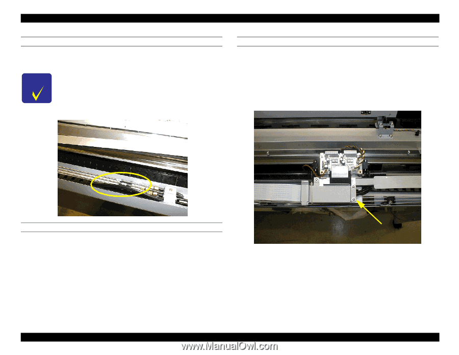
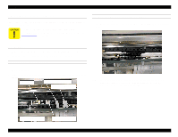
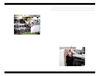
EPSON Stylus Pro 9000 CHECKING THE INK TUBES Move the carriage all the way back and forth to make sure the tubes do not come loose from the open section of the tube guide when the CR is moving. If a tube sticks out as far as the top of tube guide, check the twisting of the ink tube in the tube guide, and fix as needed. CONNECTING THE CARRIAGE FFCS 1. Make sure the FFCs are properly overlapped; the one with the shorter end should be underneath and the one with the longer end should be on top. 2. Slide the ferrite core pieces onto the FFCs. 3. Put the FFCs on the tube guide fixing plate, and make sure the fold of the FFCs lines up with the FFC connectors on the CR board. Also, make sure there is no gap between the tube guide, FFCs, and protective film sheets. 4. Attach the new cable support. Wrong ATTACHING THE CR CIRCUIT BOARD 1. Secure the CR circuit board assembly to the cable connection plate with two screws. 2. Slide the flat core pieces onto the two printhead FFCs and connect the FFCs to the circuit board. 3. Insert the other 4 connectors into the corresponding CR board connectors. CN9 is not used. Disassembly & Assembly Cable support 97
-
 1
1 -
2
-
3
-
4
-
5
-
6
-
7
-
8
-
9
-
10
-
11
-
12
-
13
-
14
-
15
-
16
-
17
-
18
-
19
-
20
-
21
-
22
-
23
-
24
-
25
-
26
-
27
-
28
-
29
-
30
-
31
-
32
-
33
-
34
-
35
-
36
-
37
-
38
-
39
-
40
-
41
-
42
-
43
-
44
-
45
-
46
-
47
-
48
-
49
-
50
-
51
-
52
-
53
-
54
-
55
-
56
-
57
-
58
-
59
-
60
-
61
-
62
-
63
-
64
-
65
-
66
-
67
-
68
-
69
-
70
-
71
-
72
-
73
-
74
-
75
-
76
-
77
-
78
-
79
-
80
-
81
-
82
-
83
-
84
-
85
-
86
-
87
-
88
-
89
-
90
-
91
-
 92
92 -
 93
93 -
 94
94 -
 95
95 -
 96
96 -
 97
97 -
 98
98 -
 99
99 -
 100
100 -
 101
101 -
 102
102 -
103
-
104
-
105
-
106
-
107
-
108
-
109
-
110
-
111
-
112
-
113
-
114
-
115
-
116
-
117
-
118
-
119
-
120
-
121
-
122
-
123
-
124
-
125
-
126
-
127
-
128
-
129
-
130
-
131
-
132
-
133
-
134
-
135
-
136
-
137
-
138
-
139
-
140
-
141
-
142
-
143
-
144
-
145
-
146
-
147
-
148
-
149
-
150
-
151
-
152
-
153
-
154
-
155
-
156
-
157
-
158
-
159
-
160
-
161
-
162
-
163
-
164
-
165
-
166
-
167
-
168
-
169
-
170
-
171
-
172
-
173
-
174
-
175
-
176
-
177
-
178
-
179
-
180
-
181
-
182
-
183
-
184
-
185
-
186
-
187
-
188
-
189
-
190
-
191
-
192
-
193
-
194
-
195
-
196
-
197
-
198
 |
 |