Epson Stylus Pro 9000 Service Manual - Page 130
Mechanical Adjustments, Carriage Cover Height Adjustment,
 |
View all Epson Stylus Pro 9000 manuals
Add to My Manuals
Save this manual to your list of manuals |
Page 130 highlights
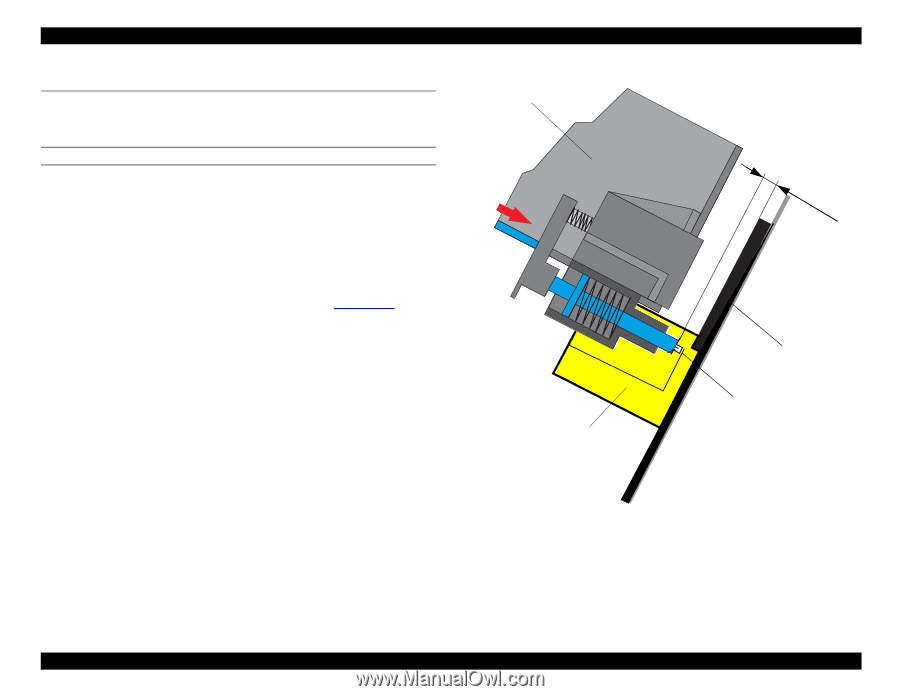
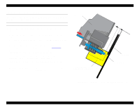
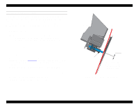
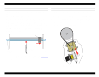
EPSON Stylus Pro 9000 5.4 Mechanical Adjustments This section describes the mechanical adjustments you need to perform when replacing or removing certain parts. CARRIAGE COVER HEIGHT ADJUSTMENT Perform this adjustment whenever you remove the carriage cover. The adjustment sets the travel distance of the cutter blade. 1. Release the Carriage Lock and move the Carriage away from home position. 2. Loosen (but do not remove) the two screws securing the Carriage Cover to the Carriage Assembly. 3. Set the Carriage Cover Position Adjustment Tool on the Subplaten (the upper surface of the Lower Paper Guide) as shown in Figure 5-14. 4. Move the Carriage over the tool so that the Cutter Blade fits into the indented gutter of the tool as shown in the figure at right. 5. Push the Carriage Cover down snugly against the Cutter Blade so that the Cutter Blade pushes down against the adjustment tool. 6. Tighten the two Carriage Cover screws, and then return the Carriage to home position. NOTE: The standard height from the cutter's bottom surface to the subplaten's upper surface is 9.75 ± 0.25 mm. Carriage Cover CR Cover Position Adjustment Tool #F724 9.75 ± 0.25mm Subplaten Cutter Blade Figure 5-14. Carriage Cover Position Adjustment Tool Adjustments 130
-
 1
1 -
2
-
3
-
4
-
5
-
6
-
7
-
8
-
9
-
10
-
11
-
12
-
13
-
14
-
15
-
16
-
17
-
18
-
19
-
20
-
21
-
22
-
23
-
24
-
25
-
26
-
27
-
28
-
29
-
30
-
31
-
32
-
33
-
34
-
35
-
36
-
37
-
38
-
39
-
40
-
41
-
42
-
43
-
44
-
45
-
46
-
47
-
48
-
49
-
50
-
51
-
52
-
53
-
54
-
55
-
56
-
57
-
58
-
59
-
60
-
61
-
62
-
63
-
64
-
65
-
66
-
67
-
68
-
69
-
70
-
71
-
72
-
73
-
74
-
75
-
76
-
77
-
78
-
79
-
80
-
81
-
82
-
83
-
84
-
85
-
86
-
87
-
88
-
89
-
90
-
91
-
92
-
93
-
94
-
95
-
96
-
97
-
98
-
99
-
100
-
101
-
102
-
103
-
104
-
105
-
106
-
107
-
108
-
109
-
110
-
111
-
112
-
113
-
114
-
115
-
116
-
117
-
118
-
119
-
120
-
121
-
122
-
123
-
124
-
 125
125 -
 126
126 -
 127
127 -
 128
128 -
 129
129 -
 130
130 -
 131
131 -
 132
132 -
 133
133 -
 134
134 -
 135
135 -
136
-
137
-
138
-
139
-
140
-
141
-
142
-
143
-
144
-
145
-
146
-
147
-
148
-
149
-
150
-
151
-
152
-
153
-
154
-
155
-
156
-
157
-
158
-
159
-
160
-
161
-
162
-
163
-
164
-
165
-
166
-
167
-
168
-
169
-
170
-
171
-
172
-
173
-
174
-
175
-
176
-
177
-
178
-
179
-
180
-
181
-
182
-
183
-
184
-
185
-
186
-
187
-
188
-
189
-
190
-
191
-
192
-
193
-
194
-
195
-
196
-
197
-
198
 |
 |