Epson Stylus Pro 9000 Service Manual - Page 103
Required Adjustments, Table 5-2., Service Parts & Required Adjustments
 |
View all Epson Stylus Pro 9000 manuals
Add to My Manuals
Save this manual to your list of manuals |
Page 103 highlights
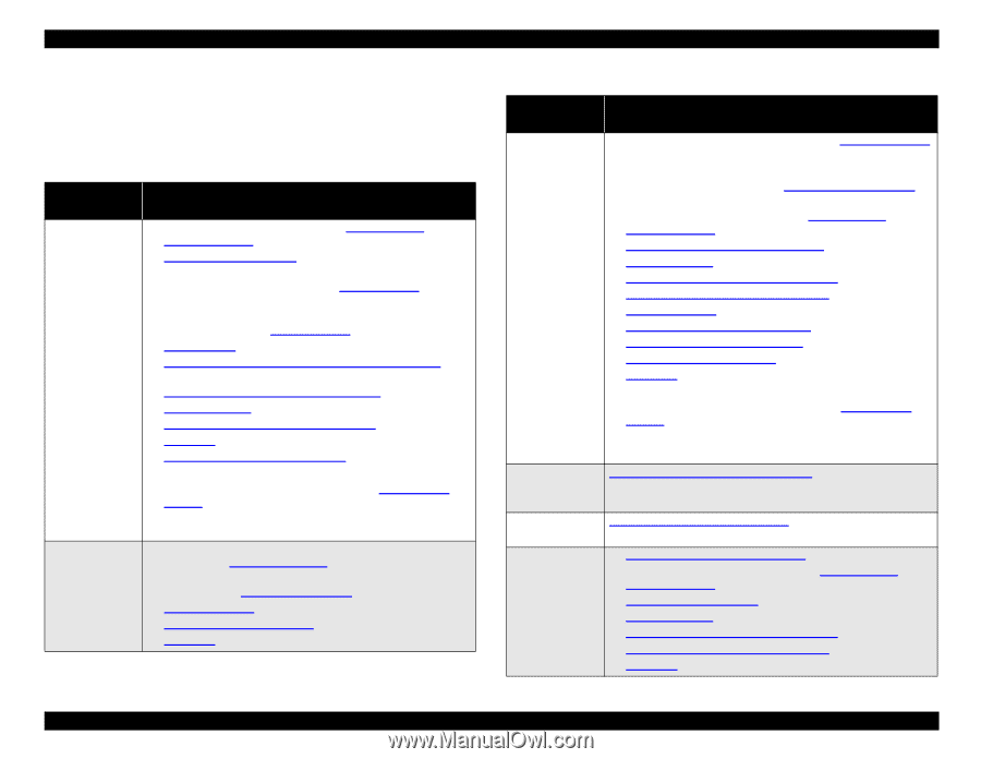
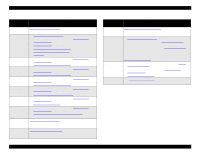
EPSON Stylus Pro 9000 5.1.3 Required Adjustments When you remove or replace parts, refer to the following table to determine which adjustments you need to perform. Always perform the adjustments in the order listed below. Table 5-2. Service Parts & Required Adjustments Service Operation Adjustment Items Printhead removal or replacement Main Board replacement (using parameter backup) 1. Enter the Self-Diagnostic Mode (see Using the SelfDiagnostic Mode on page 108) 2. Cap Position Adjustment on page 116 3. If you replaced the old printhead with a new one, perform the KK1 cleaning cycle as described in Cleaning menu on page 128. 4. If you reinstalled the old printhead, perform the KK0 cleaning cycle as described in Cleaning menu on page 128. 5. Check Nozzle on page 118 6. B Head Slant/C Head Slant Adjustment (Head Angle) on page 119 7. BC Head Slant Adjustment (Head Height) on page 120 8. Bi-D Adjustment on page 121 9. Head LR Adjustment (Head Gap Timing) on page 123 10. Test Print on page 127 11. Carriage Cover Height Adjustment on page 130 12. Turn the printer off. 13. Enter Maintenance Mode 2 as described in Maintenance Mode 2 on page 17. Select "Init. Head Unit" to reset the printhead unit counter. (Not necessary if you resintalled the old printhead.) 1. Before replacing the main board, perform the parameter backup. See Backup Procedure on page 105. 2. After replacing the main board, perform the parameter download. See Download Procedure on page 106. 3. Firmware Update on page 106 4. Sensor Trimmer Adjustment on page 136 5. Test Print on page 127 Table 5-2. Service Parts & Required Adjustments (cont.) Service Operation Adjustment Items Main Board replacement (without parameter backup) PG Motor removal or replacement 1. After replacing the Main Board, perform the Firmware Update on page 106 2. Install new ink cartridges 3. Install new Waste Ink Pads (see Maintenance Procedures on page 67) 4. Enter the Self-Diagnostic Mode (see Using the Self- Diagnostic Mode on page 108) 5. Input Rank (Printhead ID) Adjustment on page 117 6. Bi-D Adjustment on page 121 7. Head LR Adjustment (Head Gap Timing) on page 123 8. Flush Point Right and Left Adjustment on page 124 9. Feed Adjustment on page 124 10. Top & Bottom (Margin) Adjustment on page 125 11. Rear Sensor Position Adjustment on page 126 12. Sensor Trimmer Adjustment on page 136 13. Test Print on page 127 14. Turn off the printer. 15. Enter Maintenance Mode 2 as described in Maintenance Mode 2 on page 17. 16. Select "Init. Ink" to reset the ink cartridge counters. 17. Select "Init. Waste Ink" to reset the Waste Ink Pad counter. Platen Gap Gear Backlash Adjustment on page 133 CR Motor removal only CR Motor replacement Carriage Belt Tension Adjustment on page 132 1. Carriage Belt Tension Adjustment on page 132 2. Start the Self-Diagnostic Function (see Using the Self- Diagnostic Mode on page 108) 3. Cap Position Adjustment on page 116 4. Bi-D Adjustment on page 121 5. Head LR Adjustment (Head Gap Timing) on page 123 6. Flush Point Right and Left Adjustment on page 124 7. Test Print on page 127 Adjustments 103
-
 1
1 -
2
-
3
-
4
-
5
-
6
-
7
-
8
-
9
-
10
-
11
-
12
-
13
-
14
-
15
-
16
-
17
-
18
-
19
-
20
-
21
-
22
-
23
-
24
-
25
-
26
-
27
-
28
-
29
-
30
-
31
-
32
-
33
-
34
-
35
-
36
-
37
-
38
-
39
-
40
-
41
-
42
-
43
-
44
-
45
-
46
-
47
-
48
-
49
-
50
-
51
-
52
-
53
-
54
-
55
-
56
-
57
-
58
-
59
-
60
-
61
-
62
-
63
-
64
-
65
-
66
-
67
-
68
-
69
-
70
-
71
-
72
-
73
-
74
-
75
-
76
-
77
-
78
-
79
-
80
-
81
-
82
-
83
-
84
-
85
-
86
-
87
-
88
-
89
-
90
-
91
-
92
-
93
-
94
-
95
-
96
-
97
-
 98
98 -
 99
99 -
 100
100 -
 101
101 -
 102
102 -
 103
103 -
 104
104 -
 105
105 -
 106
106 -
 107
107 -
 108
108 -
109
-
110
-
111
-
112
-
113
-
114
-
115
-
116
-
117
-
118
-
119
-
120
-
121
-
122
-
123
-
124
-
125
-
126
-
127
-
128
-
129
-
130
-
131
-
132
-
133
-
134
-
135
-
136
-
137
-
138
-
139
-
140
-
141
-
142
-
143
-
144
-
145
-
146
-
147
-
148
-
149
-
150
-
151
-
152
-
153
-
154
-
155
-
156
-
157
-
158
-
159
-
160
-
161
-
162
-
163
-
164
-
165
-
166
-
167
-
168
-
169
-
170
-
171
-
172
-
173
-
174
-
175
-
176
-
177
-
178
-
179
-
180
-
181
-
182
-
183
-
184
-
185
-
186
-
187
-
188
-
189
-
190
-
191
-
192
-
193
-
194
-
195
-
196
-
197
-
198
 |
 |