Epson Stylus Pro 9000 Service Manual - Page 26
Carriage Motor and Position Control, Carriage Mechanism Sensors, Table 2-3. - cr motor
 |
View all Epson Stylus Pro 9000 manuals
Add to My Manuals
Save this manual to your list of manuals |
Page 26 highlights
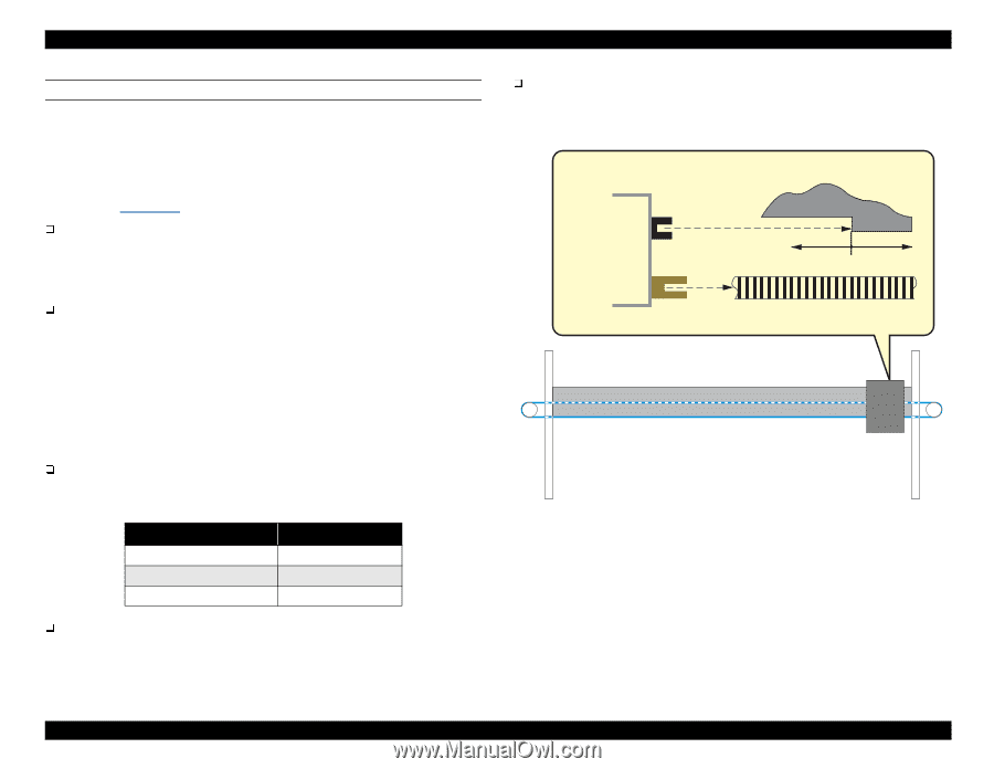
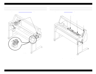
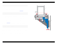
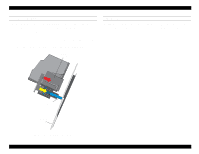
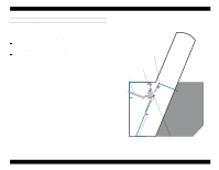
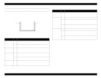
EPSON Stylus Pro 9000 CARRIAGE MOTOR AND POSITION CONTROL For the greatest possible print accuracy and to minimize vibration, the printer uses a DC motor to move the carriage. Because a rubber timing belt would stretch over the long distance the carriage must travel during printing, the Stylus Pro 9000's timing belt is made from steel. The following sensors are located on the carriage and control the carriage's position (see Figure 2-7): HP Sensor This optical sensor activates when the CR Guide Rail flag enters the space between the sensor's light emitter and the light receiver. The flag is located just above home position, and the HP sensor sends an ON signal when the carriage is in home position. Linear Encoder Sensor This sensor determines the position of the carriage by counting bands on the timing fence (timing strip) while the carriage is in motion. The bands have a distance equal to 180 dpi. For every band the Linear Encoder passes over, it sends a print timing pulse to the software servo system. The software servo forms a closed-loop with the CR motor and Encoder Sensor. It receives feedback from the Encoder Sensor and adjusts the current to the CR motor to maintain constant carriage speed. Carriage Speed and Acceleration Carriage Speed The carriage speed during printing is described below. Table 2-3. Carriage Speed Print Mode 720 dpi & Normal M/W 4 Pass FOL printing Unidirectional Carriage Speed 200 cps 300 cps 400 cps Carriage Acceleration Due to the carriage's quick acceleration, even after the heads reach and maintain normal speed, they are not stable enough to print for the next 10 mm. CR Motor Motion Failure During operation, the encoder measures the distance the carriage travels. If the CR speed as determined by the encoder varies too much from the speed set by the Software Servo, a fatal error occurs (Service Call 00010005). Carriage CR Guide Rail flag (projected area) HP Sensor Linear Encoder No HP signal HP signal Timing Strip Carriage Figure 2-7. Carriage Mechanism Sensors Technical Overview 26
-
 1
1 -
2
-
3
-
4
-
5
-
6
-
7
-
8
-
9
-
10
-
11
-
12
-
13
-
14
-
15
-
16
-
17
-
18
-
19
-
20
-
 21
21 -
 22
22 -
 23
23 -
 24
24 -
 25
25 -
 26
26 -
 27
27 -
 28
28 -
 29
29 -
 30
30 -
 31
31 -
32
-
33
-
34
-
35
-
36
-
37
-
38
-
39
-
40
-
41
-
42
-
43
-
44
-
45
-
46
-
47
-
48
-
49
-
50
-
51
-
52
-
53
-
54
-
55
-
56
-
57
-
58
-
59
-
60
-
61
-
62
-
63
-
64
-
65
-
66
-
67
-
68
-
69
-
70
-
71
-
72
-
73
-
74
-
75
-
76
-
77
-
78
-
79
-
80
-
81
-
82
-
83
-
84
-
85
-
86
-
87
-
88
-
89
-
90
-
91
-
92
-
93
-
94
-
95
-
96
-
97
-
98
-
99
-
100
-
101
-
102
-
103
-
104
-
105
-
106
-
107
-
108
-
109
-
110
-
111
-
112
-
113
-
114
-
115
-
116
-
117
-
118
-
119
-
120
-
121
-
122
-
123
-
124
-
125
-
126
-
127
-
128
-
129
-
130
-
131
-
132
-
133
-
134
-
135
-
136
-
137
-
138
-
139
-
140
-
141
-
142
-
143
-
144
-
145
-
146
-
147
-
148
-
149
-
150
-
151
-
152
-
153
-
154
-
155
-
156
-
157
-
158
-
159
-
160
-
161
-
162
-
163
-
164
-
165
-
166
-
167
-
168
-
169
-
170
-
171
-
172
-
173
-
174
-
175
-
176
-
177
-
178
-
179
-
180
-
181
-
182
-
183
-
184
-
185
-
186
-
187
-
188
-
189
-
190
-
191
-
192
-
193
-
194
-
195
-
196
-
197
-
198
 |
 |