Epson Stylus Pro 9000 Service Manual - Page 165
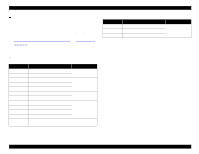
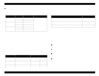
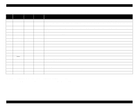
Table 7-8., Pin Assignment For Forward Channel, Pin No., Signal Name, Return, GND Pin, Direction
 |
View all Epson Stylus Pro 9000 manuals
Add to My Manuals
Save this manual to your list of manuals |
Page 165 highlights
EPSON Stylus Pro 9000 Table 7-8. Pin Assignment For Forward Channel Pin No. Signal Name Return GND Pin Direction* Functional Description 1 STROBE 19 In Data reception pulse, 0.5 uS or greater pulse width required. Usual state is HIGH, and reads data after going to LOW state. 2-9 DATA 0 to 7 20 to 7 In The DATA0 through DATA7 signals represent data bits 0 to7, respectively. Each signal is at high level when data is logical 1 and low level when data is logical 0. These signals are used to transfer the 1284 extensibility request values to the printer. 10 ACKNLG 28 Out When LOW the printer has finished preparing to receive signals and can accept data. Pulse width is about 1uS or 3uS Printer clock signal. 11 BUSY 29 Out HIGH means the printer cannot receive data. This occurs when the printer is receiving data or when the printer is in an error state. 12 PE 28 Out HIGH means no paper is loaded. (LOW means an error.) 13 SLCT 28 Out Always HIGH. Pulled up to +5V via 1.0 Kohm. 14 AFXT 30 In Not used. 15 NC Not connected. 16 GND Ground for twisted pair return. 17 Chassis Ground for frame/body. 18 Logic H Pulled up to +5 V via 3.9 Kohm. 19-30 GND Ground for twisted pair return. 31 INIT 30 In Pulse width of 50 uS or more means LOW pulse, and the falling edge of LOW signal causes the printer to initialize. 32 ERROR 29 Out LOW means printer error. 33 GND - - Ground for twisted pair return. 34 NC - - Not connected. 35 +5V - Out HIGH during normal operation. Pulled up to +5V via 1.0K ohm. 36 SLCTIN 30 In Not used. * Direction from the printer. The interface condition is normally TTL Level, and each high/low signal takes 0.2uS or less. The printer only sends data after receiving the ACKNLG confirmation or when the BUSY signal is low. Appendix 165
-
 1
1 -
2
-
3
-
4
-
5
-
6
-
7
-
8
-
9
-
10
-
11
-
12
-
13
-
14
-
15
-
16
-
17
-
18
-
19
-
20
-
21
-
22
-
23
-
24
-
25
-
26
-
27
-
28
-
29
-
30
-
31
-
32
-
33
-
34
-
35
-
36
-
37
-
38
-
39
-
40
-
41
-
42
-
43
-
44
-
45
-
46
-
47
-
48
-
49
-
50
-
51
-
52
-
53
-
54
-
55
-
56
-
57
-
58
-
59
-
60
-
61
-
62
-
63
-
64
-
65
-
66
-
67
-
68
-
69
-
70
-
71
-
72
-
73
-
74
-
75
-
76
-
77
-
78
-
79
-
80
-
81
-
82
-
83
-
84
-
85
-
86
-
87
-
88
-
89
-
90
-
91
-
92
-
93
-
94
-
95
-
96
-
97
-
98
-
99
-
100
-
101
-
102
-
103
-
104
-
105
-
106
-
107
-
108
-
109
-
110
-
111
-
112
-
113
-
114
-
115
-
116
-
117
-
118
-
119
-
120
-
121
-
122
-
123
-
124
-
125
-
126
-
127
-
128
-
129
-
130
-
131
-
132
-
133
-
134
-
135
-
136
-
137
-
138
-
139
-
140
-
141
-
142
-
143
-
144
-
145
-
146
-
147
-
148
-
149
-
150
-
151
-
152
-
153
-
154
-
155
-
156
-
157
-
158
-
159
-
 160
160 -
 161
161 -
 162
162 -
 163
163 -
 164
164 -
 165
165 -
 166
166 -
 167
167 -
 168
168 -
 169
169 -
 170
170 -
171
-
172
-
173
-
174
-
175
-
176
-
177
-
178
-
179
-
180
-
181
-
182
-
183
-
184
-
185
-
186
-
187
-
188
-
189
-
190
-
191
-
192
-
193
-
194
-
195
-
196
-
197
-
198
 |
 |
