Epson Stylus Pro 9000 Service Manual - Page 110
Test Menu, Test Menu Items, Table 5-5.
 |
View all Epson Stylus Pro 9000 manuals
Add to My Manuals
Save this manual to your list of manuals |
Page 110 highlights
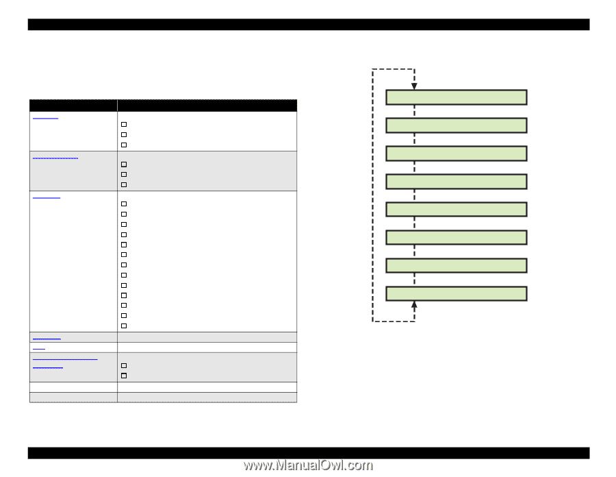
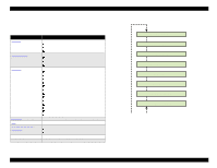
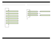
EPSON Stylus Pro 9000 5.3.3 Test Menu The Test menu lets you check the operation of the control panel, control circuits, and sensors. Table 5-5. Test Menu Items LCD Message Description Version on page 111 Control Panel on page 111 Sensors on page 112 Encoder on page 113 Fan on page 113 Elec. (Maintenance Records) on page 113. D/A Revision Head Signal Lets you check: Firmware version DIP-SW settings Control Panel and Main Board version Lets you check the operation of: Control Panel buttons LCD display LED indicators Lets you test the operation of these sensors: HP Sensor Cover Open Sensor Paper Release Lever Sensor Front Paper Sensor Rear Paper Sensor Paper Width Sensor Paper Thickness Sensor PG Sensor Printhead Thermistors I/C Holder Levers Sensors Ink ID Sensors I/C Sensors Ink Low Sensors Lets you test the CR Motor and PF Motor encoders Turns the fans on and off Lets you check: Maintenance Record (part usage and wear counters) Fatal Error Record Factory use-Head voltage correction Factory use-Head pulse check The menu items and their order in the menu are shown below. [SelecType] Test: Version Test: Panel Test: Sensor Test: Encoder Test: Fan Test: Elec. Test: D/A Revision Test: Head Signal [Paper Source] Figure 5-3. Test Menu Items NOTE: Some of the items in the Test Menu display results in hexadecimal format. The easiest way to convert hexidecimal to standard decimal notation is the use the Calculator that comes with Windows. After opening Calculator, select Scientific from the View dropdown menu. Adjustments 110
-
 1
1 -
2
-
3
-
4
-
5
-
6
-
7
-
8
-
9
-
10
-
11
-
12
-
13
-
14
-
15
-
16
-
17
-
18
-
19
-
20
-
21
-
22
-
23
-
24
-
25
-
26
-
27
-
28
-
29
-
30
-
31
-
32
-
33
-
34
-
35
-
36
-
37
-
38
-
39
-
40
-
41
-
42
-
43
-
44
-
45
-
46
-
47
-
48
-
49
-
50
-
51
-
52
-
53
-
54
-
55
-
56
-
57
-
58
-
59
-
60
-
61
-
62
-
63
-
64
-
65
-
66
-
67
-
68
-
69
-
70
-
71
-
72
-
73
-
74
-
75
-
76
-
77
-
78
-
79
-
80
-
81
-
82
-
83
-
84
-
85
-
86
-
87
-
88
-
89
-
90
-
91
-
92
-
93
-
94
-
95
-
96
-
97
-
98
-
99
-
100
-
101
-
102
-
103
-
104
-
 105
105 -
 106
106 -
 107
107 -
 108
108 -
 109
109 -
 110
110 -
 111
111 -
 112
112 -
 113
113 -
 114
114 -
 115
115 -
116
-
117
-
118
-
119
-
120
-
121
-
122
-
123
-
124
-
125
-
126
-
127
-
128
-
129
-
130
-
131
-
132
-
133
-
134
-
135
-
136
-
137
-
138
-
139
-
140
-
141
-
142
-
143
-
144
-
145
-
146
-
147
-
148
-
149
-
150
-
151
-
152
-
153
-
154
-
155
-
156
-
157
-
158
-
159
-
160
-
161
-
162
-
163
-
164
-
165
-
166
-
167
-
168
-
169
-
170
-
171
-
172
-
173
-
174
-
175
-
176
-
177
-
178
-
179
-
180
-
181
-
182
-
183
-
184
-
185
-
186
-
187
-
188
-
189
-
190
-
191
-
192
-
193
-
194
-
195
-
196
-
197
-
198
 |
 |