Epson Stylus Pro 9000 Service Manual - Page 50
No Ink Output from One or Both Printheads, Uneven Printing or Poor Resolution - head change
 |
View all Epson Stylus Pro 9000 manuals
Add to My Manuals
Save this manual to your list of manuals |
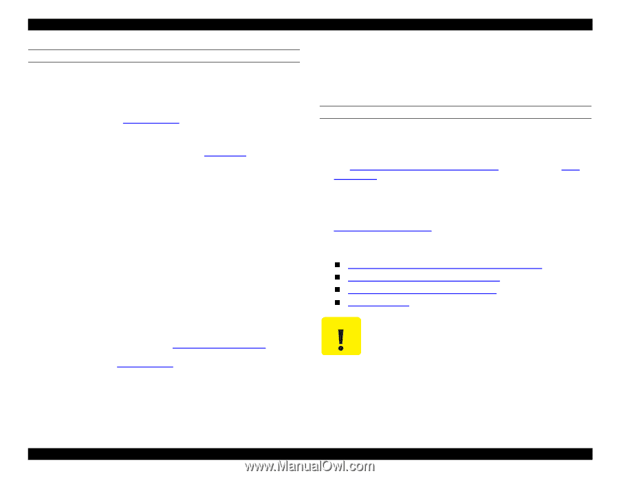
Page 50 highlights
EPSON Stylus Pro 9000 NO INK OUTPUT FROM ONE OR BOTH PRINTHEADS If there is no ink output from one or both printheads, try each of these steps in succession until the problem is resolved: 1. Make sure the ink valve on the outer side of each I/H assembly is open. (The small arrow should point to "OPEN.") Then perform an initial ink charge as described in Cleaning menu on page 128. Run a test print and check for output. 2. There may be a problem with the ink valve or tubing. To test, place a syringe on the end of one of the dampers (see Figure 4-27 on page 73). Try to draw ink through it. If ink cannot be drawn through the damper, the ink valves may be defective or the ink tubing blocked. Service these parts as needed. 3. The Capping Assembly may be damaged or clogged. Remove the Capping Assembly and rinse it in cold water. Inspect the edges of the rubber seal. If damaged, replace the Capping Assembly. Place a syringe on the tubing leading from the bottom of the Capping Assembly and try to draw water through it. If water cannot be pulled through, replace the Capping Assembly. 4. Reinstall the Capping Assembly, Pump Mechanism, and tubing in the printer. Make sure the tubing from the Capping Assembly isn't pinched or crimped. Then move the carriage to home position. Place a syringe on the end of the tubing that leads to the Flushing Box (Right). Slowly (to avoid damaging the printhead) try to draw ink through the tubing. If ink cannot be drawn through the tubing, there is a problem with the seal between the Capping Assembly and the printhead. 5. The Pump Mechanism may be defective. Turn the printer on and perform the capping position adjustment. See Cap Position Adjustment on page 116. Turn the printer off, turn it back on, and then run a cleaning cycle as described in Cleaning menu on page 128. While the cleaning cycle is running, watch the end of the tubing leading to the Flushing Box (Right). If ink does not flow through the tubing, replace the Pump Mechanism. If these steps do not restore printhead operation, the problem is probably not mechanical. Check the electrical connections between the Main Board and the printheads. Check that the Main Board is producing printhead driving signals and that the signals are reaching the printheads. Replace the Main Board or printheads as needed. UNEVEN PRINTING OR POOR RESOLUTION If printout quality suffers from unevenness, poor quality, or similar problems, check the following: 1. Perform the Head Gap and Bi-D Adjustments See Head LR Adjustment (Head Gap Timing) on page 123 and Bi-D Adjustment on page 121. 2. If the printing problem occurs only when the user prints on thick paper, press the SelecType button until the "Paper Configuration" menu appears and set the correct paper thickness. (Depending on the paper-thickness setting, the location where the ink strikes the paper may change.) See Paper Configuration Menu on page 16. 3. If the printout quality still has not improved, perform the following adjustments in the order listed below: B Head Slant/C Head Slant Adjustment (Head Angle) on page 119 BC Head Slant Adjustment (Head Height) on page 120 Head LR Adjustment (Head Gap Timing) on page 123 Bi-D Adjustment on page 121 Even if you performed the Head Gap and Bi-D Adjustments in step 1, you must perform them again after doing the Head Angle and Head Height Adjustments in step 3. Troubleshooting 50
-
 1
1 -
2
-
3
-
4
-
5
-
6
-
7
-
8
-
9
-
10
-
11
-
12
-
13
-
14
-
15
-
16
-
17
-
18
-
19
-
20
-
21
-
22
-
23
-
24
-
25
-
26
-
27
-
28
-
29
-
30
-
31
-
32
-
33
-
34
-
35
-
36
-
37
-
38
-
39
-
40
-
41
-
42
-
43
-
44
-
 45
45 -
 46
46 -
 47
47 -
 48
48 -
 49
49 -
 50
50 -
 51
51 -
 52
52 -
 53
53 -
 54
54 -
 55
55 -
56
-
57
-
58
-
59
-
60
-
61
-
62
-
63
-
64
-
65
-
66
-
67
-
68
-
69
-
70
-
71
-
72
-
73
-
74
-
75
-
76
-
77
-
78
-
79
-
80
-
81
-
82
-
83
-
84
-
85
-
86
-
87
-
88
-
89
-
90
-
91
-
92
-
93
-
94
-
95
-
96
-
97
-
98
-
99
-
100
-
101
-
102
-
103
-
104
-
105
-
106
-
107
-
108
-
109
-
110
-
111
-
112
-
113
-
114
-
115
-
116
-
117
-
118
-
119
-
120
-
121
-
122
-
123
-
124
-
125
-
126
-
127
-
128
-
129
-
130
-
131
-
132
-
133
-
134
-
135
-
136
-
137
-
138
-
139
-
140
-
141
-
142
-
143
-
144
-
145
-
146
-
147
-
148
-
149
-
150
-
151
-
152
-
153
-
154
-
155
-
156
-
157
-
158
-
159
-
160
-
161
-
162
-
163
-
164
-
165
-
166
-
167
-
168
-
169
-
170
-
171
-
172
-
173
-
174
-
175
-
176
-
177
-
178
-
179
-
180
-
181
-
182
-
183
-
184
-
185
-
186
-
187
-
188
-
189
-
190
-
191
-
192
-
193
-
194
-
195
-
196
-
197
-
198
 |
 |