Epson Stylus Pro 9000 Service Manual - Page 59
Top Cover Removal
 |
View all Epson Stylus Pro 9000 manuals
Add to My Manuals
Save this manual to your list of manuals |
Page 59 highlights
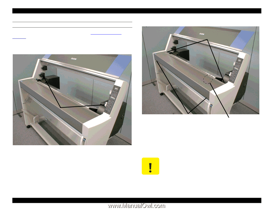
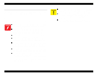
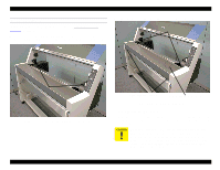
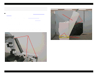
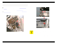
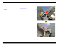
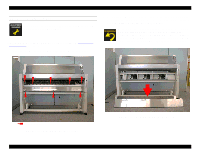
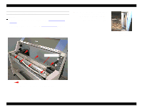
EPSON Stylus Pro 9000 TOP COVER REMOVAL Preparation: Remove the Maintenance Cover. See Maintenance Cover Removal on page 58. 1. Remove the four screws, CP(W2) M4x12, that secure the left-side lower mounting bracket (spindle holder) and remove the bracket. Repeat for the right-side lower mounting bracket. 2. Remove the four screws securing the Top Cover to the printer. CP(W2) M4x6 screws Mounting brackets (lower) Figure 4-4. Lower Mounting Bracket Removal Disassembly & Assembly CP(W2) M3x6 screws Paper Thickness Sensor Figure 4-5. Top Cover Removal 3. Lower the Paper Release Lever. 4. Slide the Top Cover slightly forward to free it from its mounting brackets in back. Then lift the Top Cover from the rear, tilting it forward, and lift it away from the printer. When removing the Top Cover, avoiding catching its rear edge on the Paper Thickness sensor, which may knock it out of adjustment. The sensor's approximate location is shown in the figure above. You can also flex the back side of the Top Cover slightly outward, toward the rear of the printer, while removing the cover. 59
-
 1
1 -
2
-
3
-
4
-
5
-
6
-
7
-
8
-
9
-
10
-
11
-
12
-
13
-
14
-
15
-
16
-
17
-
18
-
19
-
20
-
21
-
22
-
23
-
24
-
25
-
26
-
27
-
28
-
29
-
30
-
31
-
32
-
33
-
34
-
35
-
36
-
37
-
38
-
39
-
40
-
41
-
42
-
43
-
44
-
45
-
46
-
47
-
48
-
49
-
50
-
51
-
52
-
53
-
 54
54 -
 55
55 -
 56
56 -
 57
57 -
 58
58 -
 59
59 -
 60
60 -
 61
61 -
 62
62 -
 63
63 -
 64
64 -
65
-
66
-
67
-
68
-
69
-
70
-
71
-
72
-
73
-
74
-
75
-
76
-
77
-
78
-
79
-
80
-
81
-
82
-
83
-
84
-
85
-
86
-
87
-
88
-
89
-
90
-
91
-
92
-
93
-
94
-
95
-
96
-
97
-
98
-
99
-
100
-
101
-
102
-
103
-
104
-
105
-
106
-
107
-
108
-
109
-
110
-
111
-
112
-
113
-
114
-
115
-
116
-
117
-
118
-
119
-
120
-
121
-
122
-
123
-
124
-
125
-
126
-
127
-
128
-
129
-
130
-
131
-
132
-
133
-
134
-
135
-
136
-
137
-
138
-
139
-
140
-
141
-
142
-
143
-
144
-
145
-
146
-
147
-
148
-
149
-
150
-
151
-
152
-
153
-
154
-
155
-
156
-
157
-
158
-
159
-
160
-
161
-
162
-
163
-
164
-
165
-
166
-
167
-
168
-
169
-
170
-
171
-
172
-
173
-
174
-
175
-
176
-
177
-
178
-
179
-
180
-
181
-
182
-
183
-
184
-
185
-
186
-
187
-
188
-
189
-
190
-
191
-
192
-
193
-
194
-
195
-
196
-
197
-
198
 |
 |