Epson Stylus Pro 9000 Service Manual - Page 87
Removing the side cover of I/H assembly, Removing the friction gear assembly.
 |
View all Epson Stylus Pro 9000 manuals
Add to My Manuals
Save this manual to your list of manuals |
Page 87 highlights
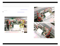
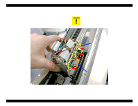
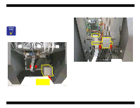
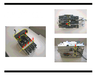
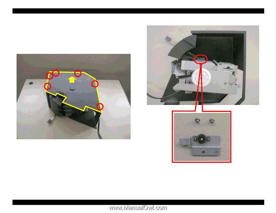
EPSON Stylus Pro 9000 8. Remove the six screws (CP(W2) M2x4) securing the side cover of the I/H assembly and remove the side cover. 9. Slightly rotate the I/C holder assembly so that the assembly is released from the lock lever unit. Then remove the two screws (CP(W2) M3x6) securing the friction gear assembly and remove the assembly. Remove Figure 4-53. Removing the side cover of I/H assembly Disassembly & Assembly Figure 4-54. Removing the friction gear assembly. 87
-
 1
1 -
2
-
3
-
4
-
5
-
6
-
7
-
8
-
9
-
10
-
11
-
12
-
13
-
14
-
15
-
16
-
17
-
18
-
19
-
20
-
21
-
22
-
23
-
24
-
25
-
26
-
27
-
28
-
29
-
30
-
31
-
32
-
33
-
34
-
35
-
36
-
37
-
38
-
39
-
40
-
41
-
42
-
43
-
44
-
45
-
46
-
47
-
48
-
49
-
50
-
51
-
52
-
53
-
54
-
55
-
56
-
57
-
58
-
59
-
60
-
61
-
62
-
63
-
64
-
65
-
66
-
67
-
68
-
69
-
70
-
71
-
72
-
73
-
74
-
75
-
76
-
77
-
78
-
79
-
80
-
81
-
 82
82 -
 83
83 -
 84
84 -
 85
85 -
 86
86 -
 87
87 -
 88
88 -
 89
89 -
 90
90 -
 91
91 -
 92
92 -
93
-
94
-
95
-
96
-
97
-
98
-
99
-
100
-
101
-
102
-
103
-
104
-
105
-
106
-
107
-
108
-
109
-
110
-
111
-
112
-
113
-
114
-
115
-
116
-
117
-
118
-
119
-
120
-
121
-
122
-
123
-
124
-
125
-
126
-
127
-
128
-
129
-
130
-
131
-
132
-
133
-
134
-
135
-
136
-
137
-
138
-
139
-
140
-
141
-
142
-
143
-
144
-
145
-
146
-
147
-
148
-
149
-
150
-
151
-
152
-
153
-
154
-
155
-
156
-
157
-
158
-
159
-
160
-
161
-
162
-
163
-
164
-
165
-
166
-
167
-
168
-
169
-
170
-
171
-
172
-
173
-
174
-
175
-
176
-
177
-
178
-
179
-
180
-
181
-
182
-
183
-
184
-
185
-
186
-
187
-
188
-
189
-
190
-
191
-
192
-
193
-
194
-
195
-
196
-
197
-
198
 |
 |
EPSON Stylus Pro 9000
Disassembly & Assembly
87
8.
Remove the six screws (CP(W2) M2x4) securing the side cover of the I/H
assembly and remove the side cover.
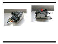
9.
Slightly rotate the I/C holder assembly so that the assembly is released
from the lock lever unit. Then remove the two screws (CP(W2) M3x6)
securing the friction gear assembly and remove the assembly.
Figure 4-53.
Removing the side cover of I/H assembly
Figure 4-54.
Removing the friction gear assembly.
Remove