Epson Stylus Pro 9000 Service Manual - Page 95
Ink Tubing Reassembly, Installing the cable connection plate
 |
View all Epson Stylus Pro 9000 manuals
Add to My Manuals
Save this manual to your list of manuals |
Page 95 highlights
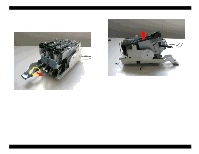
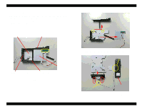
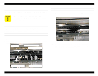
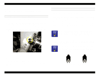
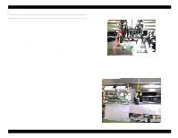
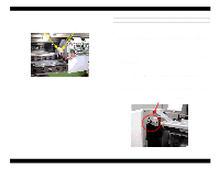
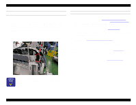
EPSON Stylus Pro 9000 4.7.1 Ink Tubing Reassembly This section describes how to re-assemble the ink tubes and related components. INSTALLING THE CABLE CONNECTION PLATE 1. Attach the HP position and Linear Encoder sensor assemblies to the cable connection plate. 2. Re-attach the cable connection plate while making sure the Timing Fence is in the middle of the Linear Encoder sensor. Lightly secure the cable connection plate with two screws, and connect the ground to the screw on the left. While looking through the hole on the right side frame to make sure the timing fence is exactly in the middle of the sensor, tighten the cable connection plate screws. POSITIONING THE TUBE GUIDES AND FFCS 1. Line up the new FFCs and make sure their folds overlap; one FFC will fit into the fold of the other. The double-sided tape (white) on one of the FFC cables must be showing on top. 2. Lay down the FFCs in the H Top frame with the multi-folded end protruding through the hole in the right-side frame. With the double-sided tape facing the front wall of the H Top frame, put the FFCs in the clips. The fold in the middle of the FFCs should be right in the middle of the printer. 3. Lay the left-side bottom layer protective film down on the left side and put the new FFCs on top of that film. Lay the next left-side protective film on top of the FFCs, and then lay the new tube guide for the light ink on top of the film. The side of the tube guide that has only four joints must attach to the ink pipes in the center. The side with seven joints must attach to the ink dampers in the carriage. Look through this hole to line up the encoder sensor and the timing fence. 3. Pull the printhead FFCs through the uppper-rear slot in the cable connection plate. While pulling the ends of the FFCs to remove any slack, secure the printhead FFCs and the H cable plate with two screws. 4. Fold the right FFC slightly in the middle so the lengths of the two FFCs are the same. 4. Lay down the right side protective film, and put the new tube guide for the dark inks on top of the film. Make sure there are only four joints on the ink pipe end of the tube guide. Make sure the three ink tubes in the tube guides are straight and in a constant triangle throughout the tube guides to prevent the tubes from overlapping, twisting, or pinching. Dark color tubes Light color tubes C LM B M Y LC Looking at the tubes from the ink pipes' point of view Disassembly & Assembly 95
-
 1
1 -
2
-
3
-
4
-
5
-
6
-
7
-
8
-
9
-
10
-
11
-
12
-
13
-
14
-
15
-
16
-
17
-
18
-
19
-
20
-
21
-
22
-
23
-
24
-
25
-
26
-
27
-
28
-
29
-
30
-
31
-
32
-
33
-
34
-
35
-
36
-
37
-
38
-
39
-
40
-
41
-
42
-
43
-
44
-
45
-
46
-
47
-
48
-
49
-
50
-
51
-
52
-
53
-
54
-
55
-
56
-
57
-
58
-
59
-
60
-
61
-
62
-
63
-
64
-
65
-
66
-
67
-
68
-
69
-
70
-
71
-
72
-
73
-
74
-
75
-
76
-
77
-
78
-
79
-
80
-
81
-
82
-
83
-
84
-
85
-
86
-
87
-
88
-
89
-
 90
90 -
 91
91 -
 92
92 -
 93
93 -
 94
94 -
 95
95 -
 96
96 -
 97
97 -
 98
98 -
 99
99 -
 100
100 -
101
-
102
-
103
-
104
-
105
-
106
-
107
-
108
-
109
-
110
-
111
-
112
-
113
-
114
-
115
-
116
-
117
-
118
-
119
-
120
-
121
-
122
-
123
-
124
-
125
-
126
-
127
-
128
-
129
-
130
-
131
-
132
-
133
-
134
-
135
-
136
-
137
-
138
-
139
-
140
-
141
-
142
-
143
-
144
-
145
-
146
-
147
-
148
-
149
-
150
-
151
-
152
-
153
-
154
-
155
-
156
-
157
-
158
-
159
-
160
-
161
-
162
-
163
-
164
-
165
-
166
-
167
-
168
-
169
-
170
-
171
-
172
-
173
-
174
-
175
-
176
-
177
-
178
-
179
-
180
-
181
-
182
-
183
-
184
-
185
-
186
-
187
-
188
-
189
-
190
-
191
-
192
-
193
-
194
-
195
-
196
-
197
-
198
 |
 |
