Epson Stylus Pro 9000 Service Manual - Page 34
Ink Supply Mechanism,
 |
View all Epson Stylus Pro 9000 manuals
Add to My Manuals
Save this manual to your list of manuals |
Page 34 highlights
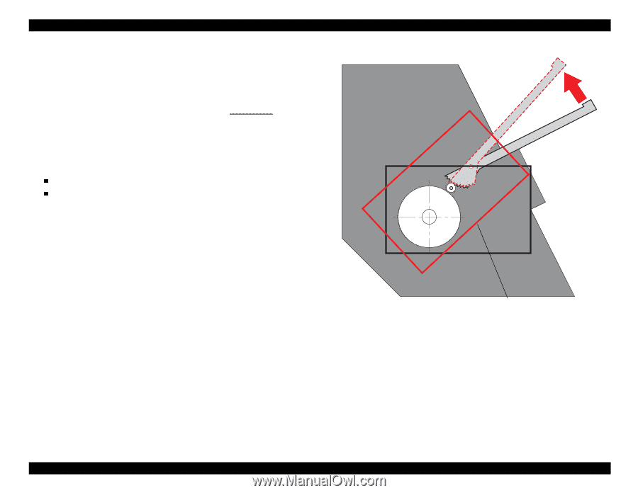
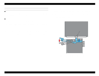
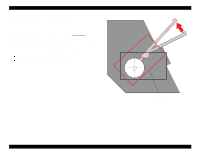
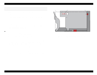
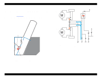
EPSON Stylus Pro 9000 2.2.4 Ink Supply Mechanism The two ink cartridge holders each hold three cartridges, K, C, and M on one side and Lc, Lm, and Y on the other side. The design of the holders makes it quite easy to install and replace ink cartridges from the front of the printer. The I/H Lever opens and closes the I/H door, and at the same time it changes the angle of the Ink Cartridge Holder Assembly as shown in Figure 2-12 on page 34. To prevent users from accidently installing a color ink cartridge in the wrong slot, the cartridges have slightly different designs. Another important feature of the ink cartridge holders is the ink valve, which is located on the outer sides of the ink cartridge holders. It can be used to shut off the flow of ink during printer transportation. The valve is closed when: the user turns the valve to the "CLOSE" position the I/H lever is lifted to install cartridges When the valves are open, the ink flows out of the ink cartridges, through the stainless steel pipes, through the ink tubes, and finally into the printheads. I/H Lever Ink Cartridge Holder Assembly Figure 2-12. Ink Supply Mechanism Technical Overview 34
-
 1
1 -
2
-
3
-
4
-
5
-
6
-
7
-
8
-
9
-
10
-
11
-
12
-
13
-
14
-
15
-
16
-
17
-
18
-
19
-
20
-
21
-
22
-
23
-
24
-
25
-
26
-
27
-
28
-
 29
29 -
 30
30 -
 31
31 -
 32
32 -
 33
33 -
 34
34 -
 35
35 -
 36
36 -
 37
37 -
 38
38 -
 39
39 -
40
-
41
-
42
-
43
-
44
-
45
-
46
-
47
-
48
-
49
-
50
-
51
-
52
-
53
-
54
-
55
-
56
-
57
-
58
-
59
-
60
-
61
-
62
-
63
-
64
-
65
-
66
-
67
-
68
-
69
-
70
-
71
-
72
-
73
-
74
-
75
-
76
-
77
-
78
-
79
-
80
-
81
-
82
-
83
-
84
-
85
-
86
-
87
-
88
-
89
-
90
-
91
-
92
-
93
-
94
-
95
-
96
-
97
-
98
-
99
-
100
-
101
-
102
-
103
-
104
-
105
-
106
-
107
-
108
-
109
-
110
-
111
-
112
-
113
-
114
-
115
-
116
-
117
-
118
-
119
-
120
-
121
-
122
-
123
-
124
-
125
-
126
-
127
-
128
-
129
-
130
-
131
-
132
-
133
-
134
-
135
-
136
-
137
-
138
-
139
-
140
-
141
-
142
-
143
-
144
-
145
-
146
-
147
-
148
-
149
-
150
-
151
-
152
-
153
-
154
-
155
-
156
-
157
-
158
-
159
-
160
-
161
-
162
-
163
-
164
-
165
-
166
-
167
-
168
-
169
-
170
-
171
-
172
-
173
-
174
-
175
-
176
-
177
-
178
-
179
-
180
-
181
-
182
-
183
-
184
-
185
-
186
-
187
-
188
-
189
-
190
-
191
-
192
-
193
-
194
-
195
-
196
-
197
-
198
 |
 |