Epson Stylus Pro 9000 Service Manual - Page 76
Removing the PF Motor Assembly, Maintenance Cover, Removal, Top Cover Removal
 |
View all Epson Stylus Pro 9000 manuals
Add to My Manuals
Save this manual to your list of manuals |
Page 76 highlights
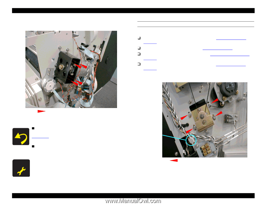
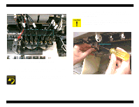
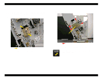
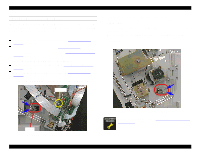
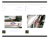
EPSON Stylus Pro 9000 5. Remove the four screws securing the CR Motor Assembly to the Right Side Frame, and then remove the CR Motor Assembly. REMOVING THE PF MOTOR ASSEMBLY Preparation: Remove the Maintenance Cover as described in Maintenance Cover Removal on page 58. Remove the Top Cover as described in Top Cover Removal on page 59. Remove the Left Side Cover as described in Left and Right Side Cover Removal on page 60. Remove the Lower Paper Guide as described in Lower Paper Guide Removal on page 63. 1. Loosen the four screws (CP(W2) M4x12) on the PF Motor Mounting Bracket as shown below to reduce the tension on the timing belt. Four CP(W2) M4x8 Figure 4-31. CR Motor Removal When re-assembling the CR Motor Assembly, move the carriage back and forth by hand, and adjust the screws in Figure 4-29 until the CR Drive Belt is centered on the pulley. (The belt must be within 1 mm of the center of the pulley.) The white CR Motor lead connects to the terminal marked "+" and the black lead connects to the terminal marked "-". After removing the CR Motor, you must perform the CR Drive Belt Tension Adjustment. PF Motor Cable Connector (black and white wires) CP(W2) M4x12 screws: only loosen Figure 4-32. Loosening the Timing Belt 2. Disconnect the PF Motor cable connector as shown in the figure above (black and white wires). Disassembly & Assembly 76
-
 1
1 -
2
-
3
-
4
-
5
-
6
-
7
-
8
-
9
-
10
-
11
-
12
-
13
-
14
-
15
-
16
-
17
-
18
-
19
-
20
-
21
-
22
-
23
-
24
-
25
-
26
-
27
-
28
-
29
-
30
-
31
-
32
-
33
-
34
-
35
-
36
-
37
-
38
-
39
-
40
-
41
-
42
-
43
-
44
-
45
-
46
-
47
-
48
-
49
-
50
-
51
-
52
-
53
-
54
-
55
-
56
-
57
-
58
-
59
-
60
-
61
-
62
-
63
-
64
-
65
-
66
-
67
-
68
-
69
-
70
-
 71
71 -
 72
72 -
 73
73 -
 74
74 -
 75
75 -
 76
76 -
 77
77 -
 78
78 -
 79
79 -
 80
80 -
 81
81 -
82
-
83
-
84
-
85
-
86
-
87
-
88
-
89
-
90
-
91
-
92
-
93
-
94
-
95
-
96
-
97
-
98
-
99
-
100
-
101
-
102
-
103
-
104
-
105
-
106
-
107
-
108
-
109
-
110
-
111
-
112
-
113
-
114
-
115
-
116
-
117
-
118
-
119
-
120
-
121
-
122
-
123
-
124
-
125
-
126
-
127
-
128
-
129
-
130
-
131
-
132
-
133
-
134
-
135
-
136
-
137
-
138
-
139
-
140
-
141
-
142
-
143
-
144
-
145
-
146
-
147
-
148
-
149
-
150
-
151
-
152
-
153
-
154
-
155
-
156
-
157
-
158
-
159
-
160
-
161
-
162
-
163
-
164
-
165
-
166
-
167
-
168
-
169
-
170
-
171
-
172
-
173
-
174
-
175
-
176
-
177
-
178
-
179
-
180
-
181
-
182
-
183
-
184
-
185
-
186
-
187
-
188
-
189
-
190
-
191
-
192
-
193
-
194
-
195
-
196
-
197
-
198
 |
 |