Epson Stylus Pro 9000 Service Manual - Page 75
Removing the Carriage Motor Assembly, Maintenance Cover, Removal, Top Cover Removal, Left and Right
 |
View all Epson Stylus Pro 9000 manuals
Add to My Manuals
Save this manual to your list of manuals |
Page 75 highlights
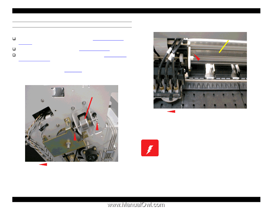
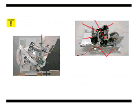
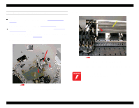
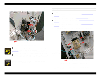
EPSON Stylus Pro 9000 REMOVING THE CARRIAGE MOTOR ASSEMBLY Preparation: Remove the Maintenance Cover as described in Maintenance Cover Removal on page 58. Remove the Top Cover as described in Top Cover Removal on page 59. Remove the Left and Right Side Covers as described in Left and Right Side Cover Removal on page 60. 1. Manually release the Carriage Lock and move the carriage away from the capping position, as shown in Figure 4-24. 2. On the Left Side Frame, loosen the two screws shown below to reduce tension on the CR Drive Belt. 3. Remove the hex screw that secures the CR Drive Belt to the right side of the carriage assembly. CR Drive Belt CR Drive Belt Pulley Remove one Hex Screw: 2.5mm Figure 4-30. Removing the CR Drive Belt 4. Pull the loose end of the Carriage Drive Belt out through the Right Side Frame. The edges of the CR drive belt may be sharp. Exercise caution when removing the belt. Loosen these two screws. Figure 4-29. Loosening the CR Drive Belt Disassembly & Assembly 75
-
 1
1 -
2
-
3
-
4
-
5
-
6
-
7
-
8
-
9
-
10
-
11
-
12
-
13
-
14
-
15
-
16
-
17
-
18
-
19
-
20
-
21
-
22
-
23
-
24
-
25
-
26
-
27
-
28
-
29
-
30
-
31
-
32
-
33
-
34
-
35
-
36
-
37
-
38
-
39
-
40
-
41
-
42
-
43
-
44
-
45
-
46
-
47
-
48
-
49
-
50
-
51
-
52
-
53
-
54
-
55
-
56
-
57
-
58
-
59
-
60
-
61
-
62
-
63
-
64
-
65
-
66
-
67
-
68
-
69
-
 70
70 -
 71
71 -
 72
72 -
 73
73 -
 74
74 -
 75
75 -
 76
76 -
 77
77 -
 78
78 -
 79
79 -
 80
80 -
81
-
82
-
83
-
84
-
85
-
86
-
87
-
88
-
89
-
90
-
91
-
92
-
93
-
94
-
95
-
96
-
97
-
98
-
99
-
100
-
101
-
102
-
103
-
104
-
105
-
106
-
107
-
108
-
109
-
110
-
111
-
112
-
113
-
114
-
115
-
116
-
117
-
118
-
119
-
120
-
121
-
122
-
123
-
124
-
125
-
126
-
127
-
128
-
129
-
130
-
131
-
132
-
133
-
134
-
135
-
136
-
137
-
138
-
139
-
140
-
141
-
142
-
143
-
144
-
145
-
146
-
147
-
148
-
149
-
150
-
151
-
152
-
153
-
154
-
155
-
156
-
157
-
158
-
159
-
160
-
161
-
162
-
163
-
164
-
165
-
166
-
167
-
168
-
169
-
170
-
171
-
172
-
173
-
174
-
175
-
176
-
177
-
178
-
179
-
180
-
181
-
182
-
183
-
184
-
185
-
186
-
187
-
188
-
189
-
190
-
191
-
192
-
193
-
194
-
195
-
196
-
197
-
198
 |
 |