Epson Stylus Pro 9000 Service Manual - Page 104
EPSON Stylus Pro 9000, Adjustments, Table 5-2., Service Parts & Required Adjustments cont.
 |
View all Epson Stylus Pro 9000 manuals
Add to My Manuals
Save this manual to your list of manuals |
Page 104 highlights
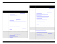
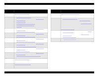
EPSON Stylus Pro 9000 Table 5-2. Service Parts & Required Adjustments (cont.) Service Operation Adjustment Items PF Motor removal only PF Belt Tension Adjustment on page 132 PF Motor replacement Front Paper Sensor removal or replacement Paper Edge Sensor removal or replacement Rear Paper Sensor removal or replacement Paper Thickness Sensor removal or replacement HP Sensor removal or replacement Cover Open Sensors (R/L) removal or replacement 1. PF Belt Tension Adjustment on page 132 2. Start the Self-Diagnostic Function (see Using the Self- Diagnostic Mode on page 108) 3. Feed Adjustment on page 124 4. Top & Bottom (Margin) Adjustment on page 125 5. Rear Sensor Position Adjustment on page 126 6. Test Print on page 127 1. Start the Self-Diagnostic Function (see Using the SelfDiagnostic Mode on page 108) 2. Top & Bottom (Margin) Adjustment on page 125 1. Start the Self-Diagnostic Function (see Using the SelfDiagnostic Mode on page 108) 2. Top & Bottom (Margin) Adjustment on page 125 1. Start the Self-Diagnostic Function (see Using the SelfDiagnostic Mode on page 108) 2. Top & Bottom (Margin) Adjustment on page 125 1. Start the Self-Diagnostic Function (see Using the SelfDiagnostic Mode on page 108) 2. Paper Thickness Sensor Adjustment on page 134 1. Start the Self-Diagnostic Function (see Using the SelfDiagnostic Mode on page 108) 2. Cap Position Adjustment on page 116 1. Start the Self-Diagnostic Function (see Using the SelfDiagnostic Mode on page 108) 2. Cover Open Sensor Assembly (Right and left) on page 135 Lower Paper Cutter Position Adjustment on page 131 Guide removal or replacement I/H Assembly removal or replacement I/H Lever Position Adjustment on page 133 Table 5-2. Service Parts & Required Adjustments (cont.) Service Operation Adjustment Items Carriage Cover removal or replacement Waste Ink Pads Maintenance Assembly Ink tube Replacement Carriage Cover Height Adjustment on page 130 1. Cutter Position Adjustment on page 131 2. Reset the waste ink counter. See Maintenance Mode 2 on page 17. 3. Reset the cleaning unit counter. See Maintenance Mode 2 on page 17. Note that you also have to replace the replaceable parts in the Maintenance Assembly when replacing the Waste Ink Pads. See Maintenance Procedures on page 67. 1. If you remove the Lower Paper Guide, perform the Cutter Position Adjustment on page 131. 2. Enter the Self-Diagnostic Mode (see Using the Self- Diagnostic Mode on page 108). 3. Cap Position Adjustment on page 116 See Removing the Ink Tubes on page 92 for complete instructions. Adjustments 104
-
 1
1 -
2
-
3
-
4
-
5
-
6
-
7
-
8
-
9
-
10
-
11
-
12
-
13
-
14
-
15
-
16
-
17
-
18
-
19
-
20
-
21
-
22
-
23
-
24
-
25
-
26
-
27
-
28
-
29
-
30
-
31
-
32
-
33
-
34
-
35
-
36
-
37
-
38
-
39
-
40
-
41
-
42
-
43
-
44
-
45
-
46
-
47
-
48
-
49
-
50
-
51
-
52
-
53
-
54
-
55
-
56
-
57
-
58
-
59
-
60
-
61
-
62
-
63
-
64
-
65
-
66
-
67
-
68
-
69
-
70
-
71
-
72
-
73
-
74
-
75
-
76
-
77
-
78
-
79
-
80
-
81
-
82
-
83
-
84
-
85
-
86
-
87
-
88
-
89
-
90
-
91
-
92
-
93
-
94
-
95
-
96
-
97
-
98
-
 99
99 -
 100
100 -
 101
101 -
 102
102 -
 103
103 -
 104
104 -
 105
105 -
 106
106 -
 107
107 -
 108
108 -
 109
109 -
110
-
111
-
112
-
113
-
114
-
115
-
116
-
117
-
118
-
119
-
120
-
121
-
122
-
123
-
124
-
125
-
126
-
127
-
128
-
129
-
130
-
131
-
132
-
133
-
134
-
135
-
136
-
137
-
138
-
139
-
140
-
141
-
142
-
143
-
144
-
145
-
146
-
147
-
148
-
149
-
150
-
151
-
152
-
153
-
154
-
155
-
156
-
157
-
158
-
159
-
160
-
161
-
162
-
163
-
164
-
165
-
166
-
167
-
168
-
169
-
170
-
171
-
172
-
173
-
174
-
175
-
176
-
177
-
178
-
179
-
180
-
181
-
182
-
183
-
184
-
185
-
186
-
187
-
188
-
189
-
190
-
191
-
192
-
193
-
194
-
195
-
196
-
197
-
198
 |
 |