Epson Stylus Pro 9000 Service Manual - Page 94
Removing the cable connection plate, Remove the HP position head origin and Linear Encoder CR ENC
 |
View all Epson Stylus Pro 9000 manuals
Add to My Manuals
Save this manual to your list of manuals |
Page 94 highlights
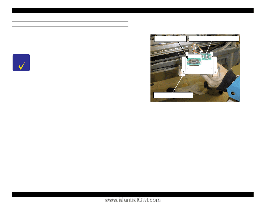
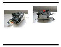
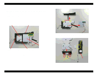
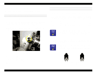
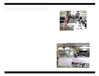
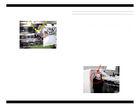
EPSON Stylus Pro 9000 REMOVING THE CABLE CONNECTION PLATE 1. Insert a screwdriver through one of the holes in the ink tube support frame, loosen the two screws securing the tube guide fixing plate on the underside of the cable connection plate, and remove the plastic ink tube guide protector on the top-right side of the cable connection plate. (Use a 100 mm to 150 mm length plus/cross head (Phillips) driver.) If the printer has been used, there is a chance the screws at either end of the ink tube support frame may be worn. The ink tube guides and cables rub these screws every time they make a pass. If the heads of the screws are worn, replace the screws. NOTE: If the replacement ink tubes do not have a O-rings and screws, remove the O-rings and screws from the old tubes and put them aside for re-use later. 2. Carefully remove the cable connection plate so as not to scratch or catch the timing fence. The carriage FFCs, tube guides, and tube guide fixing plate will come off with the cable connection plate. 3. Disconnect the FFCs from the junction board, and remove the FFCs. 4. Remove the HP position (head origin) and Linear Encoder (CR ENC) sensor assemblies from the back of the cable connection plate; you will use them again. CR ENC assembly Head origin detector assembly Cable connection plate Reverse side of cable connection plate Disassembly & Assembly 94
-
 1
1 -
2
-
3
-
4
-
5
-
6
-
7
-
8
-
9
-
10
-
11
-
12
-
13
-
14
-
15
-
16
-
17
-
18
-
19
-
20
-
21
-
22
-
23
-
24
-
25
-
26
-
27
-
28
-
29
-
30
-
31
-
32
-
33
-
34
-
35
-
36
-
37
-
38
-
39
-
40
-
41
-
42
-
43
-
44
-
45
-
46
-
47
-
48
-
49
-
50
-
51
-
52
-
53
-
54
-
55
-
56
-
57
-
58
-
59
-
60
-
61
-
62
-
63
-
64
-
65
-
66
-
67
-
68
-
69
-
70
-
71
-
72
-
73
-
74
-
75
-
76
-
77
-
78
-
79
-
80
-
81
-
82
-
83
-
84
-
85
-
86
-
87
-
88
-
 89
89 -
 90
90 -
 91
91 -
 92
92 -
 93
93 -
 94
94 -
 95
95 -
 96
96 -
 97
97 -
 98
98 -
 99
99 -
100
-
101
-
102
-
103
-
104
-
105
-
106
-
107
-
108
-
109
-
110
-
111
-
112
-
113
-
114
-
115
-
116
-
117
-
118
-
119
-
120
-
121
-
122
-
123
-
124
-
125
-
126
-
127
-
128
-
129
-
130
-
131
-
132
-
133
-
134
-
135
-
136
-
137
-
138
-
139
-
140
-
141
-
142
-
143
-
144
-
145
-
146
-
147
-
148
-
149
-
150
-
151
-
152
-
153
-
154
-
155
-
156
-
157
-
158
-
159
-
160
-
161
-
162
-
163
-
164
-
165
-
166
-
167
-
168
-
169
-
170
-
171
-
172
-
173
-
174
-
175
-
176
-
177
-
178
-
179
-
180
-
181
-
182
-
183
-
184
-
185
-
186
-
187
-
188
-
189
-
190
-
191
-
192
-
193
-
194
-
195
-
196
-
197
-
198
 |
 |