Epson Stylus Pro 9000 Service Manual - Page 57
Order of Disassembly
 |
View all Epson Stylus Pro 9000 manuals
Add to My Manuals
Save this manual to your list of manuals |
Page 57 highlights
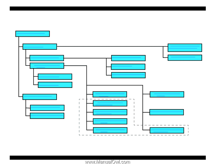
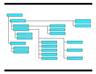
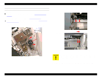
EPSON Stylus Pro 9000 4.1.4 Order of Disassembly For efficient disassembly and assembly, refer to the following flowchart. Maintenance Cover Removal on page 58 Top Cover Removal on page 70 Upper Paper Guide Removal on page 64 Left and Right Side Cover Removal on page 60 Front Cover Removal on page 61 Power Supply Board Removal on page 65 Main Board Removal on page 66 Removing the Rear Paper Sensor on page 80 Removing the Carriage Home Position Sensor and Encoder on page 82 Replacing the Printheads on page 71 Roll Cover Removal on page 62 Lower Paper Guide Removal on page 63 Replacing the Waste Ink Pads on page 67 Removing the Front Paper Sensor on page 81 To access these parts, you need to remove only the Right Side Cover Removing the Carriage Motor Assembly on page 75 Removing the Platen Gap Adjustment motor on page 78 Removing the Platen Gap Home Position Sensor on page 78 Removing the Paper Thickness Sensor on page 80 Removing the Paper Release Sensor on page 81 Figure 4-1. Disassembly Process Flowchart Removing the Cover open Sensors on page 79 To access the Left I/L Switch, you also need to remove the Upper Paper Guide Removing the PF Motor Assembly on page 76 To access the PF Motor, you also need to remove the Lower Paper Guide Maintenance Assembly Removal & Disassembly on page 69 To access the Maintenance Assembly, you also need to remove the Lower Paper Guide and Right Waste Ink Box Disassembly & Assembly 57
-
 1
1 -
2
-
3
-
4
-
5
-
6
-
7
-
8
-
9
-
10
-
11
-
12
-
13
-
14
-
15
-
16
-
17
-
18
-
19
-
20
-
21
-
22
-
23
-
24
-
25
-
26
-
27
-
28
-
29
-
30
-
31
-
32
-
33
-
34
-
35
-
36
-
37
-
38
-
39
-
40
-
41
-
42
-
43
-
44
-
45
-
46
-
47
-
48
-
49
-
50
-
51
-
 52
52 -
 53
53 -
 54
54 -
 55
55 -
 56
56 -
 57
57 -
 58
58 -
 59
59 -
 60
60 -
 61
61 -
 62
62 -
63
-
64
-
65
-
66
-
67
-
68
-
69
-
70
-
71
-
72
-
73
-
74
-
75
-
76
-
77
-
78
-
79
-
80
-
81
-
82
-
83
-
84
-
85
-
86
-
87
-
88
-
89
-
90
-
91
-
92
-
93
-
94
-
95
-
96
-
97
-
98
-
99
-
100
-
101
-
102
-
103
-
104
-
105
-
106
-
107
-
108
-
109
-
110
-
111
-
112
-
113
-
114
-
115
-
116
-
117
-
118
-
119
-
120
-
121
-
122
-
123
-
124
-
125
-
126
-
127
-
128
-
129
-
130
-
131
-
132
-
133
-
134
-
135
-
136
-
137
-
138
-
139
-
140
-
141
-
142
-
143
-
144
-
145
-
146
-
147
-
148
-
149
-
150
-
151
-
152
-
153
-
154
-
155
-
156
-
157
-
158
-
159
-
160
-
161
-
162
-
163
-
164
-
165
-
166
-
167
-
168
-
169
-
170
-
171
-
172
-
173
-
174
-
175
-
176
-
177
-
178
-
179
-
180
-
181
-
182
-
183
-
184
-
185
-
186
-
187
-
188
-
189
-
190
-
191
-
192
-
193
-
194
-
195
-
196
-
197
-
198
 |
 |