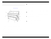
Epson Stylus Pro 9000 Service Manual - Page 7

Disassembly & Assembly, EPSON Stylus Pro 9000, Revision - dampers

Page 7 highlights

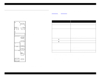
EPSON Stylus Pro 9000 Paper Not Cut 46 Paper Not Straight 46 Reload Paper 47 Push Lever Down 47 Compartment Open 47 Ink Out 48 No Ink Cartridge 48 Remove Paper 48 Option I/F Error 48 Print Quality Troubleshooting 49 Missing Dots or Lines 49 No Ink Output from One or Both Printheads 50 Uneven Printing or Poor Resolution 50 Smudged or Marred Printout (Front 51 Smudged or Marred Printout (Reverse side 51 White or Black Banding 51 Connector-Related Errors 52 4 Disassembly & Assembly Overview ...55 Precautions 55 Tools ...56 Screw List 56 Order of Disassembly 57 Housing Parts 58 Housing Removal 58 Maintenance Cover Removal 58 Top Cover Removal 59 Left and Right Side Cover Removal 60 Front Cover Removal 61 Roll Cover Removal 62 Lower Paper Guide Removal 63 Upper Paper Guide Removal 64 Circuit Board Removal 65 Power Supply Board Removal 65 Main Board Removal 66 Revision A Maintenance Procedures 67 Replacing the Waste Ink Pads 67 Maintenance Assembly Removal & Disassembly 69 Printer Mechanism Disassembly 71 Replacing the Printheads 71 Removing the Carriage Motor Assembly 75 Removing the PF Motor Assembly 76 Removing the Platen Gap Adjustment motor 78 Removing the Platen Gap Home Position Sensor 78 Removing the Cover open Sensors 79 Removing the Paper Thickness Sensor 80 Removing the Rear Paper Sensor 80 Removing the Front Paper Sensor 81 Removing the Paper Release Sensor 81 Removing the Carriage Home Position Sensor and Encoder ......... 82 Ink Holder Disassembly 84 Removing the I/C Holder Assembly 84 Disassembling the I/C Holder 91 Removing the Ink Tubes 92 Preparation 92 Removing the Ink Pipe Covers 92 Separating the ink pipes and ink tubes 92 Removing the CR circuit board 93 Disconnecting the ink dampers 93 Removing the cable connection plate 94 Ink Tubing Reassembly 95 Installing the new cable connection plate 95 Positioning the tube guides and FFCs 95 Connecting the ink tubes to the ink pipes 96 Securing the the ink tubes and ink pipes 96 Securing the tube guides on the CR side 96 Checking the ink tubes 97 Attaching the CR circuit board 97 Connecting the carriage FFCs 97 Connecting the ink tubes and dampers 98 Confirming the tube guide assembly position 99 Connecting the carriage FFCs to the relay circuit board 100 Resetting the printer 100 7

  • 1
  • 2
  • 3
  • 4
  • 5
  • 6
  • 7
  • 8
  • 9
  • 10
  • 11
  • 12
  • 13
  • 14
  • 15
  • 16
  • 17
  • 18
  • 19
  • 20
  • 21
  • 22
  • 23
  • 24
  • 25
  • 26
  • 27
  • 28
  • 29
  • 30
  • 31
  • 32
  • 33
  • 34
  • 35
  • 36
  • 37
  • 38
  • 39
  • 40
  • 41
  • 42
  • 43
  • 44
  • 45
  • 46
  • 47
  • 48
  • 49
  • 50
  • 51
  • 52
  • 53
  • 54
  • 55
  • 56
  • 57
  • 58
  • 59
  • 60
  • 61
  • 62
  • 63
  • 64
  • 65
  • 66
  • 67
  • 68
  • 69
  • 70
  • 71
  • 72
  • 73
  • 74
  • 75
  • 76
  • 77
  • 78
  • 79
  • 80
  • 81
  • 82
  • 83
  • 84
  • 85
  • 86
  • 87
  • 88
  • 89
  • 90
  • 91
  • 92
  • 93
  • 94
  • 95
  • 96
  • 97
  • 98
  • 99
  • 100
  • 101
  • 102
  • 103
  • 104
  • 105
  • 106
  • 107
  • 108
  • 109
  • 110
  • 111
  • 112
  • 113
  • 114
  • 115
  • 116
  • 117
  • 118
  • 119
  • 120
  • 121
  • 122
  • 123
  • 124
  • 125
  • 126
  • 127
  • 128
  • 129
  • 130
  • 131
  • 132
  • 133
  • 134
  • 135
  • 136
  • 137
  • 138
  • 139
  • 140
  • 141
  • 142
  • 143
  • 144
  • 145
  • 146
  • 147
  • 148
  • 149
  • 150
  • 151
  • 152
  • 153
  • 154
  • 155
  • 156
  • 157
  • 158
  • 159
  • 160
  • 161
  • 162
  • 163
  • 164
  • 165
  • 166
  • 167
  • 168
  • 169
  • 170
  • 171
  • 172
  • 173
  • 174
  • 175
  • 176
  • 177
  • 178
  • 179
  • 180
  • 181
  • 182
  • 183
  • 184
  • 185
  • 186
  • 187
  • 188
  • 189
  • 190
  • 191
  • 192
  • 193
  • 194
  • 195
  • 196
  • 197
  • 198

EPSON Stylus Pro 9000
Revision A
7
Paper Not Cut
..................................................................................
46
Paper Not Straight
...........................................................................
46
Reload Paper
...................................................................................
47
Push Lever Down
............................................................................
47
Compartment Open
.........................................................................
47
Ink Out
.............................................................................................
48
No Ink Cartridge
..............................................................................
48
Remove Paper
.................................................................................
48
Option I/F Error
................................................................................
48
Print Quality Troubleshooting
..................................................................
49
Missing Dots or Lines
......................................................................
49
No Ink Output from One or Both Printheads
....................................
50
Uneven Printing or Poor Resolution
................................................
50
Smudged or Marred Printout (Front)
...............................................
51
Smudged or Marred Printout (Reverse side)
...................................
51
White or Black Banding
...................................................................
51
Connector-Related Errors
.........................................................................
52
4
Disassembly & Assembly
Overview
.....................................................................................................
55
Precautions
............................................................................................
55
Tools
.......................................................................................................
56
Screw List
...............................................................................................
56
Order of Disassembly
.............................................................................
57
Housing Parts
.........................................................................................
58
Housing Removal
......................................................................................
58
Maintenance Cover Removal
..........................................................
58
Top Cover Removal
.........................................................................
59
Left and Right Side Cover Removal
................................................
60
Front Cover Removal
......................................................................
61
Roll Cover Removal
.........................................................................
62
Lower Paper Guide Removal
..........................................................
63
Upper Paper Guide Removal
..........................................................
64
Circuit Board Removal
..............................................................................
65
Power Supply Board Removal
.........................................................
65
Main Board Removal
.......................................................................
66
Maintenance Procedures
..........................................................................
67
Replacing the Waste Ink Pads
........................................................
67
Maintenance Assembly Removal & Disassembly
...........................
69
Printer Mechanism Disassembly
.............................................................
71
Replacing the Printheads
................................................................
71
Removing the Carriage Motor Assembly
.........................................
75
Removing the PF Motor Assembly
..................................................
76
Removing the Platen Gap Adjustment motor
..................................
78
Removing the Platen Gap Home Position Sensor
...........................
78
Removing the Cover open Sensors
.................................................
79
Removing the Paper Thickness Sensor
..........................................
80
Removing the Rear Paper Sensor
...................................................
80
Removing the Front Paper Sensor
..................................................
81
Removing the Paper Release Sensor
.............................................
81
Removing the Carriage Home Position Sensor and Encoder
.........
82
Ink Holder Disassembly
............................................................................
84
Removing the I/C Holder Assembly
.......................................................
84
Disassembling the I/C Holder
.................................................................
91
Removing the Ink Tubes
...........................................................................
92
Preparation
......................................................................................
92
Removing the Ink Pipe Covers
........................................................
92
Separating the ink pipes and ink tubes
...........................................
92
Removing the CR circuit board
........................................................
93
Disconnecting the ink dampers
.......................................................
93
Removing the cable connection plate
..............................................
94
Ink Tubing Reassembly
..........................................................................
95
Installing the new cable connection plate
........................................
95
Positioning the tube guides and FFCs
.............................................
95
Connecting the ink tubes to the ink pipes
........................................
96
Securing the the ink tubes and ink pipes
.........................................
96
Securing the tube guides on the CR side
........................................
96
Checking the ink tubes
....................................................................
97
Attaching the CR circuit board
.........................................................
97
Connecting the carriage FFCs
.........................................................
97
Connecting the ink tubes and dampers
...........................................
98
Confirming the tube guide assembly position
..................................
99
Connecting the carriage FFCs to the relay circuit board
...............
100
Resetting the printer
......................................................................
100