Yamaha LS9-32 Owner's Manual - Page 169
INSERT ON/OFF button, Input/output meters, INPUT L/R buttons, Repeatedly press the [RACK 5-8] key
 |
View all Yamaha LS9-32 manuals
Add to My Manuals
Save this manual to your list of manuals |
Page 169 highlights
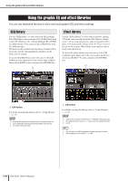
About the internal effects 3 Use the INPUT L button to open the INPUT CH SELECT popup window, and select the insert-in of the same channel as the outputdestination. Insert-in will be assigned to the L output of the effect. If you are inserting in a channel that handles a stereo source, use the same procedure to assign the insertout/insert-in of the other channel to the R input and R output of the effect. 4 Press the [HOME] key to access the SELECTED CH VIEW screen, and access the channel into which you want to insert the effect. 5 Move the cursor to the INSERT popup button, and press the [ENTER] key to access the INSERT popup window. Make sure that the desired rack is selected for the input/output ports you're using for the insertion. For details on Insert Out/In, refer to "Inserting an external device into a channel" (→ p. 101). 1 1 INSERT ON/OFF button HINT • The INSERT popup window also lets you change the insertout/in position within the channel. 6 Make sure that the INSERT ON/OFF button is turned on for the channel into which you inserted the effect. If this is off, turn it on. In this state, effect insertion is enabled for the corresponding channel. 7 Repeatedly press the [RACK 5-8] key to access the RACK screen for the rack you inserted into the channel. In this screen you can edit the parameters of the effect. The screen contains the following items. 2 13 1 Input/output meters These indicate the level of the signals before and after the effect. B INPUT L/R buttons These buttons display the OUTPUT CH SELECT popup window. The operating procedure is the same as for the INPUT button in the GEQ/EFFECT field. C OUTPUT L/R buttons These buttons display the INPUT CH SELECT popup window. The operating procedure is the same as for the OUTPUT button in the GEQ/EFFECT field. 8 Select the effect type and edit the effect parameters. For details on editing the effect parameters, refer to "Editing the internal effect parameters." HINT • The levels before and after the effect are shown by the input/ output meters at the upper right of the RACK screen. NOTE • Adjust the insert out signal level and the effect parameters so that the signal does not reach the overload point at the input or output stage of the effect. 17 Graphic EQ and effects 9 Select the fader layer that includes the channel you selected in step 3 as the output destination of the rack, and operate the corresponding fader to adjust the level appropriately. LS9-16/32 Owner's Manual 169
-
 1
1 -
2
-
3
-
4
-
5
-
6
-
7
-
8
-
9
-
10
-
11
-
12
-
13
-
14
-
15
-
16
-
17
-
18
-
19
-
20
-
21
-
22
-
23
-
24
-
25
-
26
-
27
-
28
-
29
-
30
-
31
-
32
-
33
-
34
-
35
-
36
-
37
-
38
-
39
-
40
-
41
-
42
-
43
-
44
-
45
-
46
-
47
-
48
-
49
-
50
-
51
-
52
-
53
-
54
-
55
-
56
-
57
-
58
-
59
-
60
-
61
-
62
-
63
-
64
-
65
-
66
-
67
-
68
-
69
-
70
-
71
-
72
-
73
-
74
-
75
-
76
-
77
-
78
-
79
-
80
-
81
-
82
-
83
-
84
-
85
-
86
-
87
-
88
-
89
-
90
-
91
-
92
-
93
-
94
-
95
-
96
-
97
-
98
-
99
-
100
-
101
-
102
-
103
-
104
-
105
-
106
-
107
-
108
-
109
-
110
-
111
-
112
-
113
-
114
-
115
-
116
-
117
-
118
-
119
-
120
-
121
-
122
-
123
-
124
-
125
-
126
-
127
-
128
-
129
-
130
-
131
-
132
-
133
-
134
-
135
-
136
-
137
-
138
-
139
-
140
-
141
-
142
-
143
-
144
-
145
-
146
-
147
-
148
-
149
-
150
-
151
-
152
-
153
-
154
-
155
-
156
-
157
-
158
-
159
-
160
-
161
-
162
-
163
-
 164
164 -
 165
165 -
 166
166 -
 167
167 -
 168
168 -
 169
169 -
 170
170 -
 171
171 -
 172
172 -
 173
173 -
 174
174 -
175
-
176
-
177
-
178
-
179
-
180
-
181
-
182
-
183
-
184
-
185
-
186
-
187
-
188
-
189
-
190
-
191
-
192
-
193
-
194
-
195
-
196
-
197
-
198
-
199
-
200
-
201
-
202
-
203
-
204
-
205
-
206
-
207
-
208
-
209
-
210
-
211
-
212
-
213
-
214
-
215
-
216
-
217
-
218
-
219
-
220
-
221
-
222
-
223
-
224
-
225
-
226
-
227
-
228
-
229
-
230
-
231
-
232
-
233
-
234
-
235
-
236
-
237
-
238
-
239
-
240
-
241
-
242
-
243
-
244
-
245
-
246
-
247
-
248
-
249
-
250
-
251
-
252
-
253
-
254
-
255
-
256
-
257
-
258
-
259
-
260
-
261
-
262
-
263
-
264
-
265
-
266
-
267
-
268
-
269
-
270
-
271
-
272
-
273
-
274
-
275
-
276
-
277
-
278
-
279
-
280
-
281
-
282
-
283
-
284
-
285
-
286
-
287
-
288
-
289
-
290
 |
 |
