HP Cluster Platform Interconnects v2010 Quadrics QsNetII Interconnect - Page 110

Verifying the Common Clock Source

Page 110 highlights

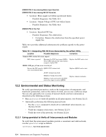
• Temperature: - The temperature for each sensor should be no higher than 40 degrees Celsius. • Fan speeds: - Fan speeds should be within a range of 2000 to 4400 rpm. • PSU status: - The power supply status should be on on (both PSUs healthy and supplying power). See Section 12.2.3 for information on verifying the clock status. 12.2.3 Verifying the Common Clock Source Normally, clock source B is a slave to clock source A, causing both generators to run at same frequency. If a interconnect detects a controller failure and fails over to its secondary control card, the cluster will continue to run because all clocks are slaves of Clock source A. However, If clock source A fails, clock source B automatically becomes master and all interconnects automatically fail over to clock source B. Viewing an interconnect's environmental status will reveal whether the clock sources are optimal. The clock source parameters must obey the following configuration rules: • The interconnects must be configured as either standalone or federated, as described in Section 9.3.1. • In bounded clusters (

  • 1
  • 2
  • 3
  • 4
  • 5
  • 6
  • 7
  • 8
  • 9
  • 10
  • 11
  • 12
  • 13
  • 14
  • 15
  • 16
  • 17
  • 18
  • 19
  • 20
  • 21
  • 22
  • 23
  • 24
  • 25
  • 26
  • 27
  • 28
  • 29
  • 30
  • 31
  • 32
  • 33
  • 34
  • 35
  • 36
  • 37
  • 38
  • 39
  • 40
  • 41
  • 42
  • 43
  • 44
  • 45
  • 46
  • 47
  • 48
  • 49
  • 50
  • 51
  • 52
  • 53
  • 54
  • 55
  • 56
  • 57
  • 58
  • 59
  • 60
  • 61
  • 62
  • 63
  • 64
  • 65
  • 66
  • 67
  • 68
  • 69
  • 70
  • 71
  • 72
  • 73
  • 74
  • 75
  • 76
  • 77
  • 78
  • 79
  • 80
  • 81
  • 82
  • 83
  • 84
  • 85
  • 86
  • 87
  • 88
  • 89
  • 90
  • 91
  • 92
  • 93
  • 94
  • 95
  • 96
  • 97
  • 98
  • 99
  • 100
  • 101
  • 102
  • 103
  • 104
  • 105
  • 106
  • 107
  • 108
  • 109
  • 110
  • 111
  • 112
  • 113
  • 114
  • 115
  • 116
  • 117
  • 118
  • 119
  • 120
  • 121
  • 122
  • 123
  • 124
  • 125
  • 126
  • 127
  • 128
  • 129
  • 130
  • 131
  • 132
  • 133
  • 134
  • 135
  • 136
  • 137
  • 138
  • 139
  • 140
  • 141
  • 142
  • 143
  • 144
  • 145
  • 146
  • 147
  • 148
  • 149
  • 150
  • 151
  • 152
  • 153
  • 154
  • 155
  • 156
  • 157
  • 158
  • 159
  • 160
  • 161
  • 162
  • 163
  • 164
  • 165
  • 166

Temperature:
– The temperature for each sensor should be no higher than 40
degrees Celsius.
Fan speeds:
– Fan speeds should be within a range of 2000 to 4400 rpm.
PSU status:
– The power supply status should be
on on
(both PSUs healthy
and supplying power).
See Section 12.2.3 for information on verifying the clock status.
12.2.3 Verifying the Common Clock Source
Normally, clock source B is a slave to clock source A, causing both generators to
run at same frequency. If a interconnect detects a controller failure and fails
over to its secondary control card, the cluster will continue to run because all
clocks are slaves of Clock source A. However, If clock source A fails, clock source
B automatically becomes master and all interconnects automatically fail over to
clock source B. Viewing an interconnect’s environmental status will reveal whether
the clock sources are optimal.
The clock source parameters must obey the following configuration rules:
The interconnects must be configured as either standalone or federated, as
described in Section 9.3.1.
In bounded clusters (<128 nodes) , the clock source is always set to local.
In federated clusters (128–256 nodes):
-
The clock source is always set to external.
-
All interconnects use the same source.
The clock source must be operating in a frequency range of 663 MHz to 667 Mhz.
12.2.3.1
Clock Source Information from the qsnetstat Utility
Refer to the output display from the
qsnetstat
utility, described in Section 12.2.1.
The following data fields provide information on the
Switch Module State
clock
source parameters:
ClkSrc
– The clock source that is currently in use, which might be A or B.
ClkFreq
– The clock frequency.
Clock
– Both source and frequency (truncated) in the format
A/656
or
B/656
.
Clock Errors
– This relates to data traffic timing errors, not problems with
the clock sources.
12.2.3.2
Clock Source Information from the jtest Utility
Refer to the output display from the
jtest
utility, shown in Example 11-1. The
following data fields provide information on the clock source parameters:
Redundant
– This will be yes or no, depending on the mode of the interconnect,
which you configured in Section 9.3.1.
Federated
– This will be yes or no, depending on the mode of the interconnect,
which you configured in Section 9.3.1.
ClockSource
– This will be
local
or
external
, depending on the
interconnect’s mode configuration.
Freq:
– The clock frequency should be in the range of 663 MHz to 667 MHz.
12-8
Maintenance and Diagnostic Procedures