HP Cluster Platform Interconnects v2010 Quadrics QsNetII Interconnect - Page 35
The post-installation verification procedure includes a clock verification task.
 |
View all HP Cluster Platform Interconnects v2010 manuals
Add to My Manuals
Save this manual to your list of manuals |
Page 35 highlights
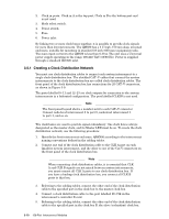
6. Repeat steps 1-5 until all interconnect controller cards are cabled to their respective clock boxes. 7. Connect the synchronization cable between the clock boxes, as specified in the cabling tables. 8. Ensure that the clock mode switches are set to master for clock box A and Slave for clock box B. 9. The post-installation verification procedure includes a clock verification task. Ensure that the complete clock network is visible and the clock has a frequency of 665 MHz (plus or minus 0.5 MHz). 128-Port Interconnect Modules 3-11
-
 1
1 -
2
-
3
-
4
-
5
-
6
-
7
-
8
-
9
-
10
-
11
-
12
-
13
-
14
-
15
-
16
-
17
-
18
-
19
-
20
-
21
-
22
-
23
-
24
-
25
-
26
-
27
-
28
-
29
-
 30
30 -
 31
31 -
 32
32 -
 33
33 -
 34
34 -
 35
35 -
 36
36 -
 37
37 -
 38
38 -
 39
39 -
 40
40 -
41
-
42
-
43
-
44
-
45
-
46
-
47
-
48
-
49
-
50
-
51
-
52
-
53
-
54
-
55
-
56
-
57
-
58
-
59
-
60
-
61
-
62
-
63
-
64
-
65
-
66
-
67
-
68
-
69
-
70
-
71
-
72
-
73
-
74
-
75
-
76
-
77
-
78
-
79
-
80
-
81
-
82
-
83
-
84
-
85
-
86
-
87
-
88
-
89
-
90
-
91
-
92
-
93
-
94
-
95
-
96
-
97
-
98
-
99
-
100
-
101
-
102
-
103
-
104
-
105
-
106
-
107
-
108
-
109
-
110
-
111
-
112
-
113
-
114
-
115
-
116
-
117
-
118
-
119
-
120
-
121
-
122
-
123
-
124
-
125
-
126
-
127
-
128
-
129
-
130
-
131
-
132
-
133
-
134
-
135
-
136
-
137
-
138
-
139
-
140
-
141
-
142
-
143
-
144
-
145
-
146
-
147
-
148
-
149
-
150
-
151
-
152
-
153
-
154
-
155
-
156
-
157
-
158
-
159
-
160
-
161
-
162
-
163
-
164
-
165
-
166
 |
 |

6.
Repeat steps 1-5 until all interconnect controller cards are cabled to their
respective clock boxes.
7.
Connect the synchronization cable between the clock boxes, as specified in
the cabling tables.
8.
Ensure that the clock mode switches are set to master for clock box A and
Slave for clock box B.
9.
The post-installation verification procedure includes a clock verification task.
Ensure that the complete clock network is visible and the clock has a frequency
of 665 MHz (plus or minus 0.5 MHz).
128-Port Interconnect Modules
3-11