HP Cluster Platform Interconnects v2010 Quadrics QsNetII Interconnect - Page 80
Setting or Viewing The Controller Card Mode
 |
View all HP Cluster Platform Interconnects v2010 manuals
Add to My Manuals
Save this manual to your list of manuals |
Page 80 highlights
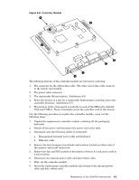
can further be determined by the interconnect cabling labels. (See the cabling tables for a description of the labeling syntax). Each interconnect chassis has a unique name that describes its address and location in the network topology. A typical chassis name is QR0N00 and the default TCP/IP addresses are shown in Table 9-1. Table 9-1: Interconnect Names and TCP/IP Addresses TCP/IP Address Interconnect Chassis Name 172.20.66.1 to 172.20.66.8 QR0N00 - QR0N07 172.20.66.9 to 172.20.66.12 QR0T00 - QR0T03 The interconnect chassis names in Table 9-1 contain an Nxx to distinguish node-level chassis and a Txx to distinguish top-level chassis. This distinction is explained in the HP Cluster Platform Overview and Site Planning Guide, and in the cabling tables. The integer xx is the chassis number. In a 1024-way network, the range for top-level interconnects is 0-7 and the range for node-level interconnects 0-15. In a 256-way network, the range for top-level interconnects is 0-1 and the range for node-level interconnects is 0-3. • You must know the Ethernet TCP/IP addresses assigned to each interconnect controller. By default, the TCP/IP addresses used for preinstalled clusters are as follows: There are three separate procedures that make up a complete postinstallation verification. You might also use these same procedures when diagnosing cluster problems or when replacing an interconnect's controller card: • Setting or viewing the controller card mode, (see Section 9.3.1). • Setting the controller card TCP/IP addresses, (see Section 9.3.2). • Performing the postinstallation verification procedure, (see Section 9.4). 9.3.1 Setting or Viewing The Controller Card Mode This menu option enables you to set the mode of the controller card. You can toggle the interconnect between the following modes: • Non-federated - In this mode the interconnect must be part of a bounded cluster that has less than 128 nodes, otherwise known as a standalone interconnect. • Federated - In this mode the interconnect must be part of a federated cluster that has more than 128 nodes and thus requires more than one interconnect chassis to service the network. • Redundant - If a second controller card is installed you can enable redundant mode so that the interconnect fails over from a non-functioning controller. Perform the following procedures to verify or configure the interconnect's controller card settings: 1. Open a connection to the control processor as described in Section 9.2. The main menu is displayed, as shown in Example 9-1. 2. Select the option titled: 4. Set module mode from the main menu. The following prompt is displayed: Set Federated? (y or n, q to abort) Enter y if the interconnect is part of a federated cluster , or n if the interconnect is standalone. Enter q to abort the process and retain the current settings. 3. A second prompt is displayed as follows: Set Redundant? (y or n, q to abort) Enter y. (All HP Cluster Platforms are shipped with redundant controllers). 9-4 Postinstallation Configuration and Testing
-
 1
1 -
2
-
3
-
4
-
5
-
6
-
7
-
8
-
9
-
10
-
11
-
12
-
13
-
14
-
15
-
16
-
17
-
18
-
19
-
20
-
21
-
22
-
23
-
24
-
25
-
26
-
27
-
28
-
29
-
30
-
31
-
32
-
33
-
34
-
35
-
36
-
37
-
38
-
39
-
40
-
41
-
42
-
43
-
44
-
45
-
46
-
47
-
48
-
49
-
50
-
51
-
52
-
53
-
54
-
55
-
56
-
57
-
58
-
59
-
60
-
61
-
62
-
63
-
64
-
65
-
66
-
67
-
68
-
69
-
70
-
71
-
72
-
73
-
74
-
 75
75 -
 76
76 -
 77
77 -
 78
78 -
 79
79 -
 80
80 -
 81
81 -
 82
82 -
 83
83 -
 84
84 -
 85
85 -
86
-
87
-
88
-
89
-
90
-
91
-
92
-
93
-
94
-
95
-
96
-
97
-
98
-
99
-
100
-
101
-
102
-
103
-
104
-
105
-
106
-
107
-
108
-
109
-
110
-
111
-
112
-
113
-
114
-
115
-
116
-
117
-
118
-
119
-
120
-
121
-
122
-
123
-
124
-
125
-
126
-
127
-
128
-
129
-
130
-
131
-
132
-
133
-
134
-
135
-
136
-
137
-
138
-
139
-
140
-
141
-
142
-
143
-
144
-
145
-
146
-
147
-
148
-
149
-
150
-
151
-
152
-
153
-
154
-
155
-
156
-
157
-
158
-
159
-
160
-
161
-
162
-
163
-
164
-
165
-
166
 |
 |
