HP Cluster Platform Interconnects v2010 Quadrics QsNetII Interconnect - Page 70
Installing the Rack Rails
 |
View all HP Cluster Platform Interconnects v2010 manuals
Add to My Manuals
Save this manual to your list of manuals |
Page 70 highlights
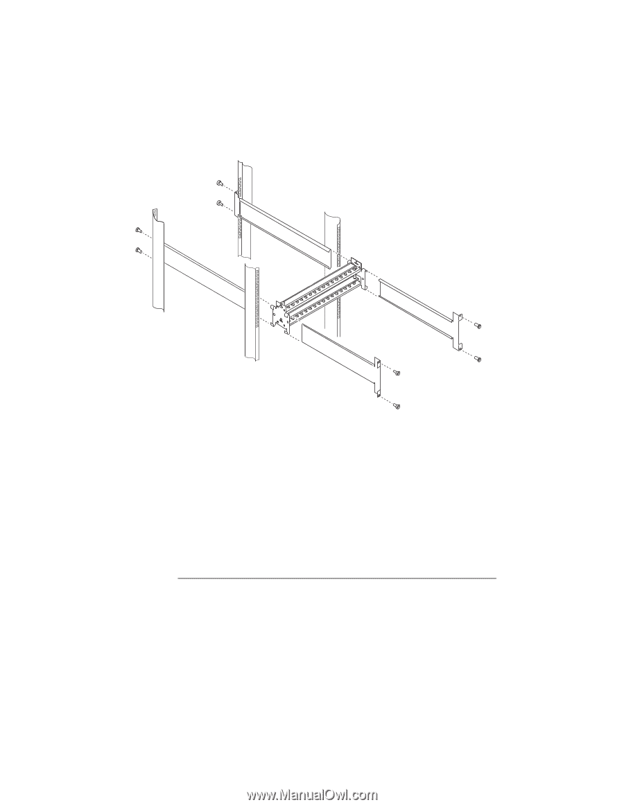
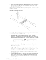
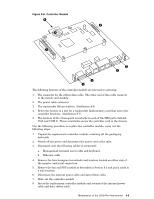
9. Secure both the cable management upper retainer and the cable management lower retainer to the right hand cable management slide by using an M4 x 10 mm knurled-head bolt. When you have assembled the cable management components, you mount it on the rack kit as shown in . Figure 8-3: Installing the Rack Rails Use the following procedure to assemble the rail kit and install the interconnect in the rack. The chassis installs with its link ports facing to the rear of the rack and its fans facing toward the front of the rack: 1. Identify the M4 x 10 mm cross-head screws that you will use for the installation. You require the same number of M4 cage nuts that clip into the back of the rack's square mounting holes. Do not use any other type of fastener. Note Use a torque driver set to 30 in-lb to set the fasteners to the correct torque. 2. Locate the correct rack installation location (U) for your model of HP Cluster platform. For example, in a dense UBB, the interconnect occupies rack location U1 through U4. 3. Clip two cage nuts to the back of each rack column, and fasten the two rear tracks to the rack columns by using four screws (two in each column). Do not tighten the screws at this time. (No screw thread should show, but the screws should be loose enough to allow for minor adjustment of the track). 4. Slid the cable retention assembly over the rear tracks and push it towards the rear of the rack. 5. Clip two cage nuts to the rear of each of the front columns, and slide the front tracks into the rear tracks until the flange rests against the front columns. Ensure that the rails are level and square and that the screw-holes align with the cage nuts. 8-4 Maintenance of the 16/32-Port Interconnect
-
 1
1 -
2
-
3
-
4
-
5
-
6
-
7
-
8
-
9
-
10
-
11
-
12
-
13
-
14
-
15
-
16
-
17
-
18
-
19
-
20
-
21
-
22
-
23
-
24
-
25
-
26
-
27
-
28
-
29
-
30
-
31
-
32
-
33
-
34
-
35
-
36
-
37
-
38
-
39
-
40
-
41
-
42
-
43
-
44
-
45
-
46
-
47
-
48
-
49
-
50
-
51
-
52
-
53
-
54
-
55
-
56
-
57
-
58
-
59
-
60
-
61
-
62
-
63
-
64
-
 65
65 -
 66
66 -
 67
67 -
 68
68 -
 69
69 -
 70
70 -
 71
71 -
 72
72 -
 73
73 -
 74
74 -
 75
75 -
76
-
77
-
78
-
79
-
80
-
81
-
82
-
83
-
84
-
85
-
86
-
87
-
88
-
89
-
90
-
91
-
92
-
93
-
94
-
95
-
96
-
97
-
98
-
99
-
100
-
101
-
102
-
103
-
104
-
105
-
106
-
107
-
108
-
109
-
110
-
111
-
112
-
113
-
114
-
115
-
116
-
117
-
118
-
119
-
120
-
121
-
122
-
123
-
124
-
125
-
126
-
127
-
128
-
129
-
130
-
131
-
132
-
133
-
134
-
135
-
136
-
137
-
138
-
139
-
140
-
141
-
142
-
143
-
144
-
145
-
146
-
147
-
148
-
149
-
150
-
151
-
152
-
153
-
154
-
155
-
156
-
157
-
158
-
159
-
160
-
161
-
162
-
163
-
164
-
165
-
166
 |
 |