HP Cluster Platform Interconnects v2010 Quadrics QsNetII Interconnect - Page 76
Replacing the Controller Module's Battery, 7 Replacing the Compact Flash Firmware Card
 |
View all HP Cluster Platform Interconnects v2010 manuals
Add to My Manuals
Save this manual to your list of manuals |
Page 76 highlights
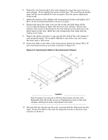
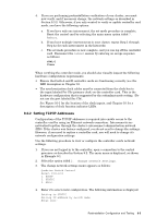
9. Secure the module by replacing the four hexagonal screwlocks and washers. 10. Replace the fan and PSU Module as described in Section 8.3. 11. Reconnect the cables that you disconnected in step 3. Reconnect the power cable. 12. Pack up the defective module using the materials supplied and return it to HP for repair or replacement. 8.6 Replacing the Controller Module's Battery Replace the battery only with a type CR2032 battery or equivalent. Dispose of used batteries according to the manufacturer's instructions. Warning There is a danger of explosion if the you do not replace the lithium battery in accordance with the following procedure. Use the following procedure to replace the battery in a controller module. Although it is a little difficult to access the battery by this method, you can replace it without removing the controller module from the chassis as described in Section 8.5: 1. Remove the fan and PSU module from the chassis, as described in Section 8.3. 2. Observe the orientation and polarity of the battery, which is installed with its positive pole upward as shown by callout 3 in Figure 8-8. 3. Carefully slide the battery from under its metal retainer clip holding it in place on he controller card and fit the replacement, 4. Replace the fan and PSU module in the chassis, as described in Section 8.3. If you find it too difficult to reach and replace the battery by this method, remove the controller module as described in Section 8.5. 8.7 Replacing the Compact Flash (Firmware) Card Use the following procedure to replace the compact flash card that stores the controller firmware. You can replace the card easily, without removing the controller module from the chassis: 1. Obtain a replacement flash card only from HP. You need only perform this operation if HP authorizes and supports an update to the firmware. 2. Remove the fan and PSU module from the chassis, as described in Section 8.3. 3. Press the ejector button (located to the right of the metal holder) on the card slot to eject the flash card from the controller module as shown by callout 4 in Figure 8-8. 4. Insert the replacement flash card by pushing it carefully into the metal holder. 5. Replace the fan and PSU module in the chassis, as described in Section 8.3. 8-10 Maintenance of the 16/32-Port Interconnect
-
 1
1 -
2
-
3
-
4
-
5
-
6
-
7
-
8
-
9
-
10
-
11
-
12
-
13
-
14
-
15
-
16
-
17
-
18
-
19
-
20
-
21
-
22
-
23
-
24
-
25
-
26
-
27
-
28
-
29
-
30
-
31
-
32
-
33
-
34
-
35
-
36
-
37
-
38
-
39
-
40
-
41
-
42
-
43
-
44
-
45
-
46
-
47
-
48
-
49
-
50
-
51
-
52
-
53
-
54
-
55
-
56
-
57
-
58
-
59
-
60
-
61
-
62
-
63
-
64
-
65
-
66
-
67
-
68
-
69
-
70
-
 71
71 -
 72
72 -
 73
73 -
 74
74 -
 75
75 -
 76
76 -
 77
77 -
 78
78 -
 79
79 -
 80
80 -
 81
81 -
82
-
83
-
84
-
85
-
86
-
87
-
88
-
89
-
90
-
91
-
92
-
93
-
94
-
95
-
96
-
97
-
98
-
99
-
100
-
101
-
102
-
103
-
104
-
105
-
106
-
107
-
108
-
109
-
110
-
111
-
112
-
113
-
114
-
115
-
116
-
117
-
118
-
119
-
120
-
121
-
122
-
123
-
124
-
125
-
126
-
127
-
128
-
129
-
130
-
131
-
132
-
133
-
134
-
135
-
136
-
137
-
138
-
139
-
140
-
141
-
142
-
143
-
144
-
145
-
146
-
147
-
148
-
149
-
150
-
151
-
152
-
153
-
154
-
155
-
156
-
157
-
158
-
159
-
160
-
161
-
162
-
163
-
164
-
165
-
166
 |
 |
