HP Cluster Platform Interconnects v2010 Quadrics QsNetII Interconnect - Page 64
Replacing a Midplane
 |
View all HP Cluster Platform Interconnects v2010 manuals
Add to My Manuals
Save this manual to your list of manuals |
Page 64 highlights
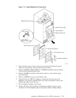
7.6.5 Electromagnetic Interference (EMI) Adhere to the following guidelines to ensure that the interconnect meets its EMI specifications when operating: 1. All clock I/O connections must be made using the specified QM584 CAT-VE double-screened (foil and braid) cables that are identified by the correct FRU part number. Do not use any other CAT-VE cables. 2. All network I/O connections must be made using specified cable assemblies that are identified by the correct FRU part number. 3. Ensure that the cables are fully inserted, locked in position and have the required cable management support to ensure connector mating angles are within the acceptable limits. 4. Replace cables if they show any signs of damage. 5. All unused switch card ports must have a QM574 shielded connector cover installed. 6. All switch ports must have spring finger connector clips installed with all spring fingers contacting the cable connector housing. Replace the clips if they show any signs of damage. 7. If removing or replacing modules ensure the spring finger gaskets on switch cards, fan trays, and controller cards show no signs of damage. 8. All unused module slots must be installed with an appropriate blank or filler module. 7.7 Replacing a Midplane Use the following procedure to remove and replace a midplane: 1. Familiarize yourself with the components shown in Figure 7-11 and read the installation instructions supplied with the midplane kit. The instructions supplied with the kit might supersede the instructions in this procedure. Verify the kit contents. 7-16 Installation and Maintenance of the 128-Port Interconnect
-
 1
1 -
2
-
3
-
4
-
5
-
6
-
7
-
8
-
9
-
10
-
11
-
12
-
13
-
14
-
15
-
16
-
17
-
18
-
19
-
20
-
21
-
22
-
23
-
24
-
25
-
26
-
27
-
28
-
29
-
30
-
31
-
32
-
33
-
34
-
35
-
36
-
37
-
38
-
39
-
40
-
41
-
42
-
43
-
44
-
45
-
46
-
47
-
48
-
49
-
50
-
51
-
52
-
53
-
54
-
55
-
56
-
57
-
58
-
 59
59 -
 60
60 -
 61
61 -
 62
62 -
 63
63 -
 64
64 -
 65
65 -
 66
66 -
 67
67 -
 68
68 -
 69
69 -
70
-
71
-
72
-
73
-
74
-
75
-
76
-
77
-
78
-
79
-
80
-
81
-
82
-
83
-
84
-
85
-
86
-
87
-
88
-
89
-
90
-
91
-
92
-
93
-
94
-
95
-
96
-
97
-
98
-
99
-
100
-
101
-
102
-
103
-
104
-
105
-
106
-
107
-
108
-
109
-
110
-
111
-
112
-
113
-
114
-
115
-
116
-
117
-
118
-
119
-
120
-
121
-
122
-
123
-
124
-
125
-
126
-
127
-
128
-
129
-
130
-
131
-
132
-
133
-
134
-
135
-
136
-
137
-
138
-
139
-
140
-
141
-
142
-
143
-
144
-
145
-
146
-
147
-
148
-
149
-
150
-
151
-
152
-
153
-
154
-
155
-
156
-
157
-
158
-
159
-
160
-
161
-
162
-
163
-
164
-
165
-
166
 |
 |