HP Cluster Platform Interconnects v2010 Quadrics QsNetII Interconnect - Page 59
Cable Management Bars, 3.8 Powering Up the Interconnect
 |
View all HP Cluster Platform Interconnects v2010 manuals
Add to My Manuals
Save this manual to your list of manuals |
Page 59 highlights
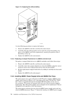
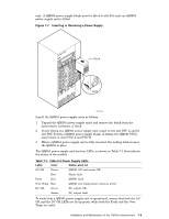
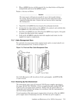
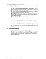
3. When a QM562 fan tray is fully inserted, the two slam latches will clip shut automatically and secure the QM562 in place. Replace a fan tray as follows Caution The interconnect will operate normally for up to 120 seconds without fan cooling. Service personnel must ensure that the replacement task is completed within this time. Prepare the new fan tray before removing the existing tray. 1. Unpack the new QM562 fan tray, keeping the packaging materials. 2. Activate the two slam latches on the QM562 to be replaced, and carefully slide the QM562 out of the interconnect enclosure. 3. Insert the new QM562 fan tray. Note that the QM562 may require a firm push to ensure the slam latches have engaged. 4. Pack up the old QM562 using the materials supplied and return it to the supplier for repair or replacement. 7.3.7 Cable Management Bars For each side of an interconnect that contains witch cards, you must install a set of cable management bars, as shown in Figure 7-9. Figure 7-9: Front and Rear Cable Management Bars Rear of Rack Front of Rack See Cable Management Kit Installation Guide, part number: AA-RVWCA-TE, or later revision. 7.3.8 Powering Up the Interconnect The interconnect uses a pair of Universal 1250 W power supplies operating in the range 100-240 VAC (50/60 Hz). Power is supplied through standard IEC320 sockets on the rear panel of the enclosure. Ensure that the mains cables are adequately rated and that the wiring is in accordance with the requirements of any local wiring regulations. Correct operation of the interconnect requires that at least one of the two QM561 power supply units is functioning correctly. Provided one power supply is Installation and Maintenance of the 128-Port Interconnect 7-11
-
 1
1 -
2
-
3
-
4
-
5
-
6
-
7
-
8
-
9
-
10
-
11
-
12
-
13
-
14
-
15
-
16
-
17
-
18
-
19
-
20
-
21
-
22
-
23
-
24
-
25
-
26
-
27
-
28
-
29
-
30
-
31
-
32
-
33
-
34
-
35
-
36
-
37
-
38
-
39
-
40
-
41
-
42
-
43
-
44
-
45
-
46
-
47
-
48
-
49
-
50
-
51
-
52
-
53
-
 54
54 -
 55
55 -
 56
56 -
 57
57 -
 58
58 -
 59
59 -
 60
60 -
 61
61 -
 62
62 -
 63
63 -
 64
64 -
65
-
66
-
67
-
68
-
69
-
70
-
71
-
72
-
73
-
74
-
75
-
76
-
77
-
78
-
79
-
80
-
81
-
82
-
83
-
84
-
85
-
86
-
87
-
88
-
89
-
90
-
91
-
92
-
93
-
94
-
95
-
96
-
97
-
98
-
99
-
100
-
101
-
102
-
103
-
104
-
105
-
106
-
107
-
108
-
109
-
110
-
111
-
112
-
113
-
114
-
115
-
116
-
117
-
118
-
119
-
120
-
121
-
122
-
123
-
124
-
125
-
126
-
127
-
128
-
129
-
130
-
131
-
132
-
133
-
134
-
135
-
136
-
137
-
138
-
139
-
140
-
141
-
142
-
143
-
144
-
145
-
146
-
147
-
148
-
149
-
150
-
151
-
152
-
153
-
154
-
155
-
156
-
157
-
158
-
159
-
160
-
161
-
162
-
163
-
164
-
165
-
166
 |
 |