HP Cluster Platform Interconnects v2010 Quadrics QsNetII Interconnect - Page 97
Accessing and Using the Interconnect, Control Menu
 |
View all HP Cluster Platform Interconnects v2010 manuals
Add to My Manuals
Save this manual to your list of manuals |
Page 97 highlights
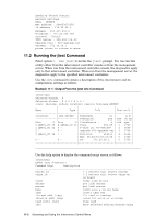
11 Accessing and Using the Interconnect Control Menu You manage single interconnects by making a connection to its controller card. For federated interconnects, the control network provides a mechanism for configuring and testing multiple interconnects. During HP Cluster Platform installation, the controller cards are linked via Cat-V Ethernet cabling to an HP ProCurve Ethernet switch. You must configure each controller card (by assigning network settings) so that you can perform management operations remotely. You can manage the interconnect either by using one of the interconnect network services, such as jtest and swctrl, or by using a telnet connection. You can make a direct connection to the controller card during initial configuration or when remote connections are unavailable. To make a direct connection, connect a serial cable to the controller card console port or connect a standard PS2 keyboard and VGA monitor to their respective ports on the controller card. See Figure 10-1 for the location of these ports. Under normal circumstances, no changes to the controller card BIOS are required. Note that BIOS settings for the controller card can only be changed by connecting a monitor and keyboard since the serial port is not enabled until later in the boot process. Both remote and direct connections to the controller card gain access to the interconnect controller operations through the interconnect control menu. When you connect to the controller card, the Quadrics Switch Control menu is displayed, as shown in Example 9-1. The following menu options launch a second menu or a procedure that is described in the relevant sections: • Showing the current network settings, (see Section 11.1). • Changing the network settings. This option was described in Section 9.3.2 as part of the interconnect configuration and installation verification procedures. • Running the jtest command, (see Section 11.2). • Setting the mode of a controller card. This option was described in Section 9.3.1 as part of the interconnect configuration and installation verification procedures. • Managing connection access to the controller card, (see Section 11.3). • Running a self test, (see Section 11.4). The procedure for upgrading the controller card firmware is described in Section 11.5. The following two options cause a command to execute immediately: • Quit - Quits the session and ends the telnet connection. You are returned to the local prompt. • Reboot - reboots the controller card firmware. A hardware reset button is also provided if the firmware hangs during any procedure. See Figure 10-2. 11.1 Showing the Network Settings Choose option 1 Show network settings to display the current settings for the interconnect, as shown in the following example: Accessing and Using the Interconnect Control Menu 11-1
-
 1
1 -
2
-
3
-
4
-
5
-
6
-
7
-
8
-
9
-
10
-
11
-
12
-
13
-
14
-
15
-
16
-
17
-
18
-
19
-
20
-
21
-
22
-
23
-
24
-
25
-
26
-
27
-
28
-
29
-
30
-
31
-
32
-
33
-
34
-
35
-
36
-
37
-
38
-
39
-
40
-
41
-
42
-
43
-
44
-
45
-
46
-
47
-
48
-
49
-
50
-
51
-
52
-
53
-
54
-
55
-
56
-
57
-
58
-
59
-
60
-
61
-
62
-
63
-
64
-
65
-
66
-
67
-
68
-
69
-
70
-
71
-
72
-
73
-
74
-
75
-
76
-
77
-
78
-
79
-
80
-
81
-
82
-
83
-
84
-
85
-
86
-
87
-
88
-
89
-
90
-
91
-
 92
92 -
 93
93 -
 94
94 -
 95
95 -
 96
96 -
 97
97 -
 98
98 -
 99
99 -
 100
100 -
 101
101 -
 102
102 -
103
-
104
-
105
-
106
-
107
-
108
-
109
-
110
-
111
-
112
-
113
-
114
-
115
-
116
-
117
-
118
-
119
-
120
-
121
-
122
-
123
-
124
-
125
-
126
-
127
-
128
-
129
-
130
-
131
-
132
-
133
-
134
-
135
-
136
-
137
-
138
-
139
-
140
-
141
-
142
-
143
-
144
-
145
-
146
-
147
-
148
-
149
-
150
-
151
-
152
-
153
-
154
-
155
-
156
-
157
-
158
-
159
-
160
-
161
-
162
-
163
-
164
-
165
-
166
 |
 |
