HP Cluster Platform Interconnects v2010 Quadrics QsNetII Interconnect - Page 12
Installation Overview
 |
View all HP Cluster Platform Interconnects v2010 manuals
Add to My Manuals
Save this manual to your list of manuals |
Page 12 highlights
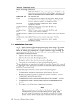
Table 1-1: Terminology (cont.) Cluster Terminology Component link QSNetII 12x EOP link cable, providing the physical link between the interconnect switch cards and the host-bus adapter in the node. Also used for the interconnect-to-interconnect links in federated clusters. management port See controller card. module A component that you install in the interconnect chassis to create a specific interconnect configuration. Switch cards, clock cards, fan trays, and power supplies are pluggable modules. node-level A specific interconnect configuration that is required for federated clusters. switch card (bottom QSNetII 16-port switch card module (ELITE4), cop- level) per interface (AB993A). switch card (third level) QSNetII 16-port switch card module (ELITE 4) with uplinks, copper interface (AB995A). switch card (reduced QSNetII 16-port switch card module (reduced links) copper (AC078A) links) switch card (no links) QSNetII Switch card (no external links) copper (AC079A) top-level A specific interconnect configuration that is required for federated clusters. 1.2 Installation Overview An HP Cluster Platform is fully integrated and tested at the factory. The cluster racks are then disconnected from each other, packed and mounted on shipping pallets for delivery to a customer site. The Site Preparation Guide describes the assembly status of the cluster when it is delivered to an installation site. It also describes the following procedures: • Removing the racks from their packaging. • Removing the racks from their shipping pallets. • Moving the racks to their final location and levelling them. • Connecting the racks together in bays and installing side panels. The preceding tasks are important and might be hazardous. Ensure that you read the appropriate safety information and follow the installation directions described in the Site Preparation Guide The installation procedure for a cluster involves the following steps: 1. Connecting and routing the interconnect cables between the racks. 2. Making any platform-specific or installation-specific connections (such as connections to optional storage racks). 3. Connecting the cluster's external network cables to the customer's network. 4. Connecting the cluster's external power cables to the appropriate power sources. 5. Powering on each of the cluster components in sequence. Note There is no master power breaker for the cluster, each rack has four circuit breakers in each of its PDUs which you can use to apply power to groups of components. An optional preinstalled operating system (such as HP XC) might require a specific power-on sequence. 1-2 Overview of Quadrics-Based Clusters
-
 1
1 -
2
-
3
-
4
-
5
-
6
-
 7
7 -
 8
8 -
 9
9 -
 10
10 -
 11
11 -
 12
12 -
 13
13 -
 14
14 -
 15
15 -
 16
16 -
 17
17 -
18
-
19
-
20
-
21
-
22
-
23
-
24
-
25
-
26
-
27
-
28
-
29
-
30
-
31
-
32
-
33
-
34
-
35
-
36
-
37
-
38
-
39
-
40
-
41
-
42
-
43
-
44
-
45
-
46
-
47
-
48
-
49
-
50
-
51
-
52
-
53
-
54
-
55
-
56
-
57
-
58
-
59
-
60
-
61
-
62
-
63
-
64
-
65
-
66
-
67
-
68
-
69
-
70
-
71
-
72
-
73
-
74
-
75
-
76
-
77
-
78
-
79
-
80
-
81
-
82
-
83
-
84
-
85
-
86
-
87
-
88
-
89
-
90
-
91
-
92
-
93
-
94
-
95
-
96
-
97
-
98
-
99
-
100
-
101
-
102
-
103
-
104
-
105
-
106
-
107
-
108
-
109
-
110
-
111
-
112
-
113
-
114
-
115
-
116
-
117
-
118
-
119
-
120
-
121
-
122
-
123
-
124
-
125
-
126
-
127
-
128
-
129
-
130
-
131
-
132
-
133
-
134
-
135
-
136
-
137
-
138
-
139
-
140
-
141
-
142
-
143
-
144
-
145
-
146
-
147
-
148
-
149
-
150
-
151
-
152
-
153
-
154
-
155
-
156
-
157
-
158
-
159
-
160
-
161
-
162
-
163
-
164
-
165
-
166
 |
 |