HP Cluster Platform Interconnects v2010 Quadrics QsNetII Interconnect - Page 34
Creating a Clock Distribution Network
 |
View all HP Cluster Platform Interconnects v2010 manuals
Add to My Manuals
Save this manual to your list of manuals |
Page 34 highlights
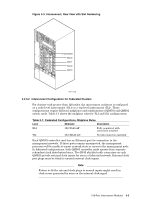
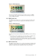
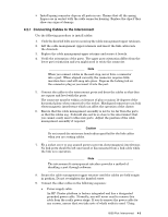
2. Clock in ports. Clock in A is the top port, Clock in B is the bottom port and is not used. 3. Mode select switch. 4. Power switch. 5. Fuse. 6. Power inlet. By linking two or more clock boxes together, it is possible to provide clock signals for more than 24 interconnects. The QM580 has a 1 U high, 170 mm deep, screened enclosure, suitable for mounting in standard 19 inch (600 mm) equipment racks. The main input current to the QM580 is less than 0.30 A. The unit uses a Universal power supply operating in the range 100-240 VAC (50/60 Hz). Power is supplied through a standard IEC320 inlet. 3.5.1 Creating a Clock Distribution Network You must use clock distribution cables to connect each system interconnect to a single clock distribution box. The shielded CAT-V cables that connect the system interconnects to the clock distribution box are called clock distribution cables. The front panel of the clock distribution box has connections for 25 CAT-V connectors, as shown in Figure 3-9. The ports labelled 0-11 and 12-23 are clock outputs for connection to the system interconnects in a federated configuration. The port labelled CLKIN is not used. Note The front panel legend shows a number next to each CAT-V connector. Connect node-level interconnect 0 to port 0, node-level interconnect 1 to port 1, and so on. Two clock boxes are used to provide signal redundancy. One clock box is always designated as the master clock, and its Master LED must be on. To create the clock distribution network, use the following procedure: 1. Identify the first interconnect enclosure, QR0N00 according to the interconnect naming conventions defined in the cabling tables. 2. Connect one end of the clock distribution cable to the CLK A port on each Quadrics system interconnect, and the other to one of the Cat-V connectors on the front panel of the clock distribution box. Note When connecting clock distribution cables, it is essential that CLK A and CLK B signals are not mixed between system interconnects; you must connect all CLK A ports to one clock distribution box. If you have a backup clock distribution box, you connect all CLK B ports to that box. 3. Referring to the cabling tables, connect the other end of the clock distribution cable to the specified port in the clock box A, the master clock box. 4. Connect a clock distribution cable to the port labelled Pri Clk in the interconnect's controller B card. 5. Referring to the cabling tables, connect the other end of the clock distribution cable to the specified port in the clock box B, the slave (redundant) clock box. 3-10 128-Port Interconnect Modules
-
 1
1 -
2
-
3
-
4
-
5
-
6
-
7
-
8
-
9
-
10
-
11
-
12
-
13
-
14
-
15
-
16
-
17
-
18
-
19
-
20
-
21
-
22
-
23
-
24
-
25
-
26
-
27
-
28
-
 29
29 -
 30
30 -
 31
31 -
 32
32 -
 33
33 -
 34
34 -
 35
35 -
 36
36 -
 37
37 -
 38
38 -
 39
39 -
40
-
41
-
42
-
43
-
44
-
45
-
46
-
47
-
48
-
49
-
50
-
51
-
52
-
53
-
54
-
55
-
56
-
57
-
58
-
59
-
60
-
61
-
62
-
63
-
64
-
65
-
66
-
67
-
68
-
69
-
70
-
71
-
72
-
73
-
74
-
75
-
76
-
77
-
78
-
79
-
80
-
81
-
82
-
83
-
84
-
85
-
86
-
87
-
88
-
89
-
90
-
91
-
92
-
93
-
94
-
95
-
96
-
97
-
98
-
99
-
100
-
101
-
102
-
103
-
104
-
105
-
106
-
107
-
108
-
109
-
110
-
111
-
112
-
113
-
114
-
115
-
116
-
117
-
118
-
119
-
120
-
121
-
122
-
123
-
124
-
125
-
126
-
127
-
128
-
129
-
130
-
131
-
132
-
133
-
134
-
135
-
136
-
137
-
138
-
139
-
140
-
141
-
142
-
143
-
144
-
145
-
146
-
147
-
148
-
149
-
150
-
151
-
152
-
153
-
154
-
155
-
156
-
157
-
158
-
159
-
160
-
161
-
162
-
163
-
164
-
165
-
166
 |
 |