HP Cluster Platform Interconnects v2010 Quadrics QsNetII Interconnect - Page 46
Cabling A QM580 Clock Distribution Box
 |
View all HP Cluster Platform Interconnects v2010 manuals
Add to My Manuals
Save this manual to your list of manuals |
Page 46 highlights
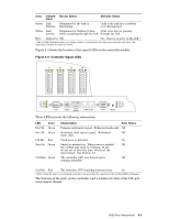
6. Determine the appropriate rack U-location for your model of HP Cluster platform. (This is usually determined by the original shipment configuration of your cluster, or by the documentation that accompanies an upgrade kit). 7. Clip four M6 cage nuts into the back of the rack at the U-location, using all three of the square mounting holes at the U-location. 8. Slide the new or replacement QM580 into the rack and align the chassis mounting holes with the cage nuts that you inserted in Step 7. 9. Secure the QM580 to the rack by using a total of four M6 machine screws (three to each column) using a torque driver set to 30 lb-in force. 10. If replacing a QM580, reattach the cables that you removed in Step 3, otherwise go to Step 11. 11. Using the Cabling Tables for your model and configuration of cluster platform, attach the data cables to the rear of the QM580, and route them to the appropriate ports in the Interconnect, as described in Section 6.2. 12. Connect the power cable and route it to the appropriate power strip. 13. If you powered down nodes and interconnects, power them up. 14. Verify that the QM580 clock distribution box is working correctly by using the test and diagnostic procedures to confirm that all interconnects are receiving a clock signal that is within the frequency specification. See Section 12.2.3. 6.2 Cabling A QM580 Clock Distribution Box The shielded Cat-V cables (QM584 clock cables) that connect the interconnects to the QM580 clock distribution box are called clock distribution cables. The front panel of the QM580 clock distribution box has connections for 25 CAT connectors. The ports labelled 0-11 and 12-23 are clock outputs for connection to the interconnects in a federated network. The front panel legend shows a number next to each Cat-V port. Node switch 0 should be connected to port 0, node switch 1 to port 1, and so on. Refer to the cabling tables for specific port-to-port cabling instructions. Caution CAUTION: When connecting clock distribution cables, it is essential that Ctrl A and Ctrl B signals are not mixed between interconnects; that is, you must connect all Ctrl A ports to one QM580 clock distribution box and connect all Ctrl B ports to a second QM580 clock distribution box. Completely install and test the Ctrl A network before configuring the Ctrl B network. Use the following procedure to make the connections: 1. Connect one end of the clock distribution cable to the Ctrl A port on each interconnect connect the other end to one of the Cat-V connectors on the front panel of the QM580 clock distribution box. 2. The clock distribution cables have RJ45 connectors at each end. Ensure that the connectors are firmly connected at each end of the cable. As each clock distribution cable is connected, label the cable with the port number and the switch number if it is not already labeled. 3. Repeat the previous steps to connect the Ctrl B port on each interconnect to a second QM580 clock distribution box to provide a backup clock. 6-2 QM580 Clock Distribution Box
-
 1
1 -
2
-
3
-
4
-
5
-
6
-
7
-
8
-
9
-
10
-
11
-
12
-
13
-
14
-
15
-
16
-
17
-
18
-
19
-
20
-
21
-
22
-
23
-
24
-
25
-
26
-
27
-
28
-
29
-
30
-
31
-
32
-
33
-
34
-
35
-
36
-
37
-
38
-
39
-
40
-
 41
41 -
 42
42 -
 43
43 -
 44
44 -
 45
45 -
 46
46 -
 47
47 -
 48
48 -
 49
49 -
 50
50 -
 51
51 -
52
-
53
-
54
-
55
-
56
-
57
-
58
-
59
-
60
-
61
-
62
-
63
-
64
-
65
-
66
-
67
-
68
-
69
-
70
-
71
-
72
-
73
-
74
-
75
-
76
-
77
-
78
-
79
-
80
-
81
-
82
-
83
-
84
-
85
-
86
-
87
-
88
-
89
-
90
-
91
-
92
-
93
-
94
-
95
-
96
-
97
-
98
-
99
-
100
-
101
-
102
-
103
-
104
-
105
-
106
-
107
-
108
-
109
-
110
-
111
-
112
-
113
-
114
-
115
-
116
-
117
-
118
-
119
-
120
-
121
-
122
-
123
-
124
-
125
-
126
-
127
-
128
-
129
-
130
-
131
-
132
-
133
-
134
-
135
-
136
-
137
-
138
-
139
-
140
-
141
-
142
-
143
-
144
-
145
-
146
-
147
-
148
-
149
-
150
-
151
-
152
-
153
-
154
-
155
-
156
-
157
-
158
-
159
-
160
-
161
-
162
-
163
-
164
-
165
-
166
 |
 |