HP Cluster Platform Interconnects v2010 Quadrics QsNetII Interconnect - Page 47
Powering Up a QM580 Clock Distribution Box, 4 Verifying or Setting the Clock Source, 5 Replacing
 |
View all HP Cluster Platform Interconnects v2010 manuals
Add to My Manuals
Save this manual to your list of manuals |
Page 47 highlights
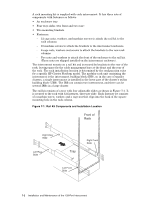
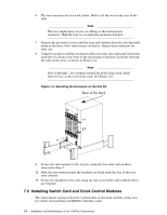
6.3 Powering Up a QM580 Clock Distribution Box The QM580 clock distribution box uses a Universal power supply operating in the range 90-254 V AC (61-49 Hz). Power is supplied through a standard IEC320 socket on the front panel. To power up a QM580 clock distribution box, perform the following steps: 1. Connect the power cable to a grounded AC power outlet and to the IEC320 power socket on the front panel of the QM580 clock distribution box. 2. Press the power supply switch (next to the IEC320 power socket) to power up the QM580 clock distribution box. Unless there is an alternate clock source available, a federated configuration will cease to function reliably when the clock distribution box is turned off. 6.4 Verifying or Setting the Clock Source The QM580 clock distribution box is set to internal clocking by default. To verify the clock source, use the qsnetstat command. A sample command is shown in the following output: # qsnetstat -ltws -Switch Module State Name IPAddr Type Build Clock PSU FanSpd Temp QR1N00 192.168.180.1 QS2_64U64D 42-4022508 A/656 O/O OOOOOO 25'C QR1N01 192.168.180.2 QS2_64U64D 42-4022508 A/656 O/O OOOOOO 24'C QR1N02 192.168.180.3 QS2_64U64D 42-4022508 A/656 O/O OOOOOO 24'C QR1N03 192.168.180.4 QS2_64U64D 42-4022508 A/656 O/O OOOOOO 26'C QR1N04 192.168.180.5 QS2_64U64D 42-4022508 A/656 O/O OOOOOO 25'C QR1N05 192.168.180.6 QS2_64U64D 42-4022508 A/656 O/O OOOOOO 26'C QR1N06 192.168.180.7 QS2_64U64D 42-4022508 A/656 O/O OOOOOO 23'C QR1N07 192.168.180.8 QS2_64U64D 42-4022508 A/656 O/O OOOOOO 23'C QR1N08 192.168.180.9 QS2_64U64D 42-4022508 A/656 X/O OOOOOO 24'C QR1N09 192.168.180.10 QS2_64U64D 41-3101510 A/656 O/O OOOOOO 23'C QR1N10 192.168.180.11 QS2_64U64D 41-3101510 A/656 O/O OOOOOO 24'C QR1N11 192.168.180.12 QS2_64U64D 42-4022508 A/656 O/O OOOOOO 24'C QR1N12 192.168.180.13 QS2_64U64D 42-4022508 A/656 O/O OOOOOO 25'C QR1N13 192.168.180.14 QS2_64U64D 42-4022508 A/656 O/O OOOOOO 25'C QR1N14 192.168.180.15 QS2_64U64D 42-4022508 A/656 O/O OOOOOO 25'C QR1T00 192.168.180.129 QS2_16X8 42-4022508 A/656 O/O OOOOOO 25'C QR1T01 192.168.180.130 QS2_16X8 42-4022508 A/656 O/O OOOOOO 28'C QR1T02 192.168.180.131 QS2_16X8 42-4022508 A/656 O/O OOOOOO 26'C QR1T03 192.168.180.132 QS2_16X8 42-4022508 A/656 O/O OOOOOO 26'C QR1T04 192.168.180.133 QS2_16X8 42-4022508 A/656 O/O OOOOOO 27'C QR1T05 192.168.180.134 QS2_16X8 42-4022508 A/656 O/O OOOOOO 26'C QR1T06 192.168.180.135 QS2_16X8 42-4022508 A/656 O/O OOOOOO 26'C QR1T07 192.168.180.136 QS2_16X8 42-4022508 A/656 O/O OOOOOO 27'C -Links In Reset See Section 12.2 for more information on the qsnetstat command. 6.5 Replacing a Fuse in the IEC AC Power Inlet Connector The fuse in the IEC AC power inlet connector is the only item in a QM580 clock distribution box that can be replaced in the field. To replace a fuse in the IEC AC power inlet connector, perform the following steps: 1. Completely disconnect the QM580 clock distribution box from the power source by removing the power cord from the front panel. 2. Remove the fuse cover. 3. Fit a new slow-blow 500 mA, 250 V, 20 mm x 5 mm ceramic fuse. There is a space within the fuse cover for storing a spare fuse for future use. 4. Replace the fuse cover. 5. Replace the power cord. QM580 Clock Distribution Box 6-3
-
 1
1 -
2
-
3
-
4
-
5
-
6
-
7
-
8
-
9
-
10
-
11
-
12
-
13
-
14
-
15
-
16
-
17
-
18
-
19
-
20
-
21
-
22
-
23
-
24
-
25
-
26
-
27
-
28
-
29
-
30
-
31
-
32
-
33
-
34
-
35
-
36
-
37
-
38
-
39
-
40
-
41
-
 42
42 -
 43
43 -
 44
44 -
 45
45 -
 46
46 -
 47
47 -
 48
48 -
 49
49 -
 50
50 -
 51
51 -
 52
52 -
53
-
54
-
55
-
56
-
57
-
58
-
59
-
60
-
61
-
62
-
63
-
64
-
65
-
66
-
67
-
68
-
69
-
70
-
71
-
72
-
73
-
74
-
75
-
76
-
77
-
78
-
79
-
80
-
81
-
82
-
83
-
84
-
85
-
86
-
87
-
88
-
89
-
90
-
91
-
92
-
93
-
94
-
95
-
96
-
97
-
98
-
99
-
100
-
101
-
102
-
103
-
104
-
105
-
106
-
107
-
108
-
109
-
110
-
111
-
112
-
113
-
114
-
115
-
116
-
117
-
118
-
119
-
120
-
121
-
122
-
123
-
124
-
125
-
126
-
127
-
128
-
129
-
130
-
131
-
132
-
133
-
134
-
135
-
136
-
137
-
138
-
139
-
140
-
141
-
142
-
143
-
144
-
145
-
146
-
147
-
148
-
149
-
150
-
151
-
152
-
153
-
154
-
155
-
156
-
157
-
158
-
159
-
160
-
161
-
162
-
163
-
164
-
165
-
166
 |
 |
