HP Cluster Platform Interconnects v2010 Quadrics QsNetII Interconnect - Page 54
Replacing QM501, QM502, and QM511C Switch Cards, 3.4 Replacing a QM511L Switch Card, 3.5
 |
View all HP Cluster Platform Interconnects v2010 manuals
Add to My Manuals
Save this manual to your list of manuals |
Page 54 highlights
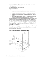
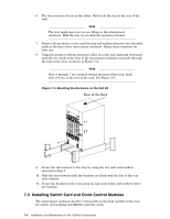
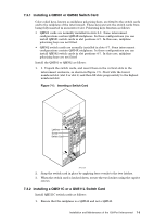
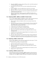
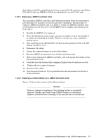
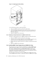
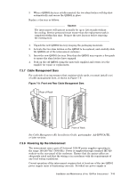
2. Unpack the QM511C modules and insert them in the vertical slots numbered 0-7 in the interconnect enclosure. 3. Start with the far left slot on the rear (slot 0) and then fill slots from left to right. 4. Snap the QM511C in place by applying force evenly to the two latches. 5. When the QM511C is located, secure the two latches using the captive screws. 6. When the rear slots are full, move onto the far right slot on the front (slot 4) and fill slots from right to left. 7. All slots numbered 0 to 7 that do not contain a QM511C should contain a QM511L. After installing all the QM511L modules, there should be no empty numbered slots. 7.3.3 Replacing QM501, QM502, and QM511C Switch Cards You can replace QM501, QM502 and QM511C modules without powering down the interconnect. Use the following procedure to replace a switch module: 1. Ensure that the cables are labeled so that you can reconnect them to the correct ports. 2. Starting at the top port, disconnect all the link cables and remove them from their support hooks on cable management bar. Take care not to bend the cables beyond their minimum bend radius. 3. Unclip and lower the hinged cable management bar. 4. Loosen the captive screw fastener on both the latches. 5. Eject the switch module by opening its two latches simultaneously. 6. Slide in the replacement switch module and engage the latches in the top and bottom rails. 7. Carefully close the latches fully, stopping if high levels of resistance are felt. 8. Tighten the two captive fasteners. 9. Raise the cable management bar and latch it into place using its spring clip. 10. Starting at the bottom port, reconnect each link cables according to its port address label. Hook the cable into the cable management bar as you proceed. 7.3.4 Replacing a QM511L Switch Card You can replace QM511L cards without powering down the interconnect. Use the following procedure to replace a top switch modules: 1. Loosen the captive fastener on both the latches. 2. Eject the switch module by opening its two latches simultaneously. 3. Slide in the replacement switch module and engage the latches in the top and bottom rails. 4. Carefully close the latches fully, stopping if high levels of resistance are felt. 5. Tighten the two captive fasteners. 7.3.5 Installing a QM503 controller Card The mechanical procedure for installing a QM503 controller card is the same as that for a switch card except that the QM503s are fitted to slots Ctrl A and Ctrl B. Either one or two QM503 controller cards may be installed in an interconnect, 7-6 Installation and Maintenance of the 128-Port Interconnect
-
 1
1 -
2
-
3
-
4
-
5
-
6
-
7
-
8
-
9
-
10
-
11
-
12
-
13
-
14
-
15
-
16
-
17
-
18
-
19
-
20
-
21
-
22
-
23
-
24
-
25
-
26
-
27
-
28
-
29
-
30
-
31
-
32
-
33
-
34
-
35
-
36
-
37
-
38
-
39
-
40
-
41
-
42
-
43
-
44
-
45
-
46
-
47
-
48
-
 49
49 -
 50
50 -
 51
51 -
 52
52 -
 53
53 -
 54
54 -
 55
55 -
 56
56 -
 57
57 -
 58
58 -
 59
59 -
60
-
61
-
62
-
63
-
64
-
65
-
66
-
67
-
68
-
69
-
70
-
71
-
72
-
73
-
74
-
75
-
76
-
77
-
78
-
79
-
80
-
81
-
82
-
83
-
84
-
85
-
86
-
87
-
88
-
89
-
90
-
91
-
92
-
93
-
94
-
95
-
96
-
97
-
98
-
99
-
100
-
101
-
102
-
103
-
104
-
105
-
106
-
107
-
108
-
109
-
110
-
111
-
112
-
113
-
114
-
115
-
116
-
117
-
118
-
119
-
120
-
121
-
122
-
123
-
124
-
125
-
126
-
127
-
128
-
129
-
130
-
131
-
132
-
133
-
134
-
135
-
136
-
137
-
138
-
139
-
140
-
141
-
142
-
143
-
144
-
145
-
146
-
147
-
148
-
149
-
150
-
151
-
152
-
153
-
154
-
155
-
156
-
157
-
158
-
159
-
160
-
161
-
162
-
163
-
164
-
165
-
166
 |
 |