HP Cluster Platform Interconnects v2010 Quadrics QsNetII Interconnect - Page 53
Installing a QM501 or QM502 Switch Card, 3.2 Installing a QM511C or a QM511L Switch Card
 |
View all HP Cluster Platform Interconnects v2010 manuals
Add to My Manuals
Save this manual to your list of manuals |
Page 53 highlights
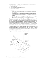
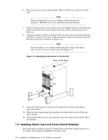
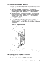
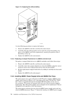
7.3.1 Installing a QM501 or QM502 Switch Card Color-coded keys, known as midplane polarizing keys, are fitted to the switch cards and to the midplane of the interconnect. These keys prevent the switch cards from being fully inserted in an incorrect slot. Polarizing keys function as follows: • QM501 cards are normally installed in slots 0-3. Some interconnect configurations contain QM54X midplanes. In these configurations you can install QM501 switch cards in slot positions 4-7. In this case, midplane polarizing keys are not fitted. • QM502 switch cards are normally installed in slots 4-7. Some interconnect configurations contain QM54X midplanes. In these configurations you can install QM502 switch cards in slot positions 4-7. In this case, midplane polarizing keys are not fitted Install the QM501 or QM502 as follows: 1. 1. Unpack the switch cards, and insert them in the vertical slots in the interconnect enclosure, as shown in Figure 7-5. Start with the lowest numbered slot (slot 0 or slot 4) and then fill slots progressively to the highest numbered slot. Figure 7-5: Inserting a Switch Card QUaDrics QsNet" PSU A Latches PSU B Screw Switch Card HPTC-0027 2. Snap the switch card in place by applying force evenly to the two latches. 3. When the switch card is latched down, secure the two latches using the captive screws. 7.3.2 Installing a QM511C or a QM511L Switch Card Install QM511C switch cards as follows: 1. Ensure that the midplane is a QM542 and not a QM540. Installation and Maintenance of the 128-Port Interconnect 7-5
-
 1
1 -
2
-
3
-
4
-
5
-
6
-
7
-
8
-
9
-
10
-
11
-
12
-
13
-
14
-
15
-
16
-
17
-
18
-
19
-
20
-
21
-
22
-
23
-
24
-
25
-
26
-
27
-
28
-
29
-
30
-
31
-
32
-
33
-
34
-
35
-
36
-
37
-
38
-
39
-
40
-
41
-
42
-
43
-
44
-
45
-
46
-
47
-
 48
48 -
 49
49 -
 50
50 -
 51
51 -
 52
52 -
 53
53 -
 54
54 -
 55
55 -
 56
56 -
 57
57 -
 58
58 -
59
-
60
-
61
-
62
-
63
-
64
-
65
-
66
-
67
-
68
-
69
-
70
-
71
-
72
-
73
-
74
-
75
-
76
-
77
-
78
-
79
-
80
-
81
-
82
-
83
-
84
-
85
-
86
-
87
-
88
-
89
-
90
-
91
-
92
-
93
-
94
-
95
-
96
-
97
-
98
-
99
-
100
-
101
-
102
-
103
-
104
-
105
-
106
-
107
-
108
-
109
-
110
-
111
-
112
-
113
-
114
-
115
-
116
-
117
-
118
-
119
-
120
-
121
-
122
-
123
-
124
-
125
-
126
-
127
-
128
-
129
-
130
-
131
-
132
-
133
-
134
-
135
-
136
-
137
-
138
-
139
-
140
-
141
-
142
-
143
-
144
-
145
-
146
-
147
-
148
-
149
-
150
-
151
-
152
-
153
-
154
-
155
-
156
-
157
-
158
-
159
-
160
-
161
-
162
-
163
-
164
-
165
-
166
 |
 |
