HP Cluster Platform Interconnects v2010 Quadrics QsNetII Interconnect - Page 23
Interconnect IP Addressing
 |
View all HP Cluster Platform Interconnects v2010 manuals
Add to My Manuals
Save this manual to your list of manuals |
Page 23 highlights
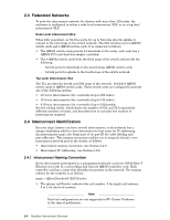
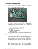
• The letter N or T indicates the type of interconnect: N for node-level; T for top-level. • The integer ICNumber is the interconnect's identification number based on its position in the hierarchy. The numbering of both node-level and top-level interconnects starts at 0 (zero). Table 2-1 shows the range of interconnect names depending on the number of nodes in the cluster. Table 2-1: Interconnect Name Ranges Number of Nodes Node Level Interconnects 8 QR0N00 64 QR0N00 128 QR0N00 256 QR0N00 - QR0N0 512 QR0N00 - QR0N0 1024 QR0N00 - QR0N15 Top Level Interconnects N/A N/A N/A QR0T00 - QR0T01 QR0T00 - QR0T04 QR0T00 - QR0T07 These names are added to the /etc/hosts file and the /etc/bootptab or /etc/dhcpd.conf file during the installation process. Note For clusters that use RMS, in addition to the switch naming convention, the modules have a physical location attribute within the RMS software, as defined by the location field in the switch_modules table. This field has the syntax: RrowNumberCcolNumberVvertIndex. See the Cabling Tables for an explanation of how the interconnect names form part of the interconnect port identifiers. These unique port identifiers are used in the nodes-to-interconnect cabling procedures. 2.4.2 Interconnect IP Addressing shows the default IP addressing for clusters in federated networks. The address is assigned to the QM503 controller card in the interconnect. The dot-quad addresses in this table represents the default IP address mapping, You can use other ranges of IP ranges if required, or if other ranges are specified by the operating environment. Switch Node Level 0-31, rail r Top Level 0-15, rail r IP Address Range 10.128.(128+r).(N+1) 10.128.(128+r).(T+128) Configuring the IP addresses is a post-installation configuration task and is described in the configuration section. Quadrics Interconnect Overview 2-5
-
 1
1 -
2
-
3
-
4
-
5
-
6
-
7
-
8
-
9
-
10
-
11
-
12
-
13
-
14
-
15
-
16
-
17
-
 18
18 -
 19
19 -
 20
20 -
 21
21 -
 22
22 -
 23
23 -
 24
24 -
 25
25 -
 26
26 -
 27
27 -
 28
28 -
29
-
30
-
31
-
32
-
33
-
34
-
35
-
36
-
37
-
38
-
39
-
40
-
41
-
42
-
43
-
44
-
45
-
46
-
47
-
48
-
49
-
50
-
51
-
52
-
53
-
54
-
55
-
56
-
57
-
58
-
59
-
60
-
61
-
62
-
63
-
64
-
65
-
66
-
67
-
68
-
69
-
70
-
71
-
72
-
73
-
74
-
75
-
76
-
77
-
78
-
79
-
80
-
81
-
82
-
83
-
84
-
85
-
86
-
87
-
88
-
89
-
90
-
91
-
92
-
93
-
94
-
95
-
96
-
97
-
98
-
99
-
100
-
101
-
102
-
103
-
104
-
105
-
106
-
107
-
108
-
109
-
110
-
111
-
112
-
113
-
114
-
115
-
116
-
117
-
118
-
119
-
120
-
121
-
122
-
123
-
124
-
125
-
126
-
127
-
128
-
129
-
130
-
131
-
132
-
133
-
134
-
135
-
136
-
137
-
138
-
139
-
140
-
141
-
142
-
143
-
144
-
145
-
146
-
147
-
148
-
149
-
150
-
151
-
152
-
153
-
154
-
155
-
156
-
157
-
158
-
159
-
160
-
161
-
162
-
163
-
164
-
165
-
166
 |
 |