HP Cluster Platform Interconnects v2010 Quadrics QsNetII Interconnect - Page 67
Installing the 16/32-Port chassis in an HP 10000 Series rack
 |
View all HP Cluster Platform Interconnects v2010 manuals
Add to My Manuals
Save this manual to your list of manuals |
Page 67 highlights
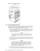
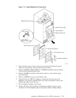
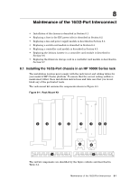
8 Maintenance of the 16/32-Port Interconnect • Installation of the chassis is described in Section 8.1 • Replacing a fuse in the IEC power inlet is described in Section 8.2. • Replacing a fan and power supply module is described in Section 8.3. • Replacing a switch card module is described in Section 8.4. • Replacing a controller card module is described in Section 8.5. • Replacing the lithium battery in a controller card module is described in Section 8.6. • Replacing the firmware storage card in a controller card module is described in Section 8.7. 8.1 Installing the 16/32-Port chassis in an HP 10000 Series rack The installation location must comply with the rack layout and cabling tables for your model of HP Cluster platform. To ensure that the correct cooling airflow is maintained, follow these installation instructions and take care that you do not block any of the perforated vents. The rack mount kit contains the components shown in Figure 8-1. Figure 8-1: Rack Mount Kit X X Y Y Z Z ]] [[ \ \ The rail kit components are identified by the figure callouts and described in Table 8-1. Maintenance of the 16/32-Port Interconnect 8-1
-
 1
1 -
2
-
3
-
4
-
5
-
6
-
7
-
8
-
9
-
10
-
11
-
12
-
13
-
14
-
15
-
16
-
17
-
18
-
19
-
20
-
21
-
22
-
23
-
24
-
25
-
26
-
27
-
28
-
29
-
30
-
31
-
32
-
33
-
34
-
35
-
36
-
37
-
38
-
39
-
40
-
41
-
42
-
43
-
44
-
45
-
46
-
47
-
48
-
49
-
50
-
51
-
52
-
53
-
54
-
55
-
56
-
57
-
58
-
59
-
60
-
61
-
 62
62 -
 63
63 -
 64
64 -
 65
65 -
 66
66 -
 67
67 -
 68
68 -
 69
69 -
 70
70 -
 71
71 -
 72
72 -
73
-
74
-
75
-
76
-
77
-
78
-
79
-
80
-
81
-
82
-
83
-
84
-
85
-
86
-
87
-
88
-
89
-
90
-
91
-
92
-
93
-
94
-
95
-
96
-
97
-
98
-
99
-
100
-
101
-
102
-
103
-
104
-
105
-
106
-
107
-
108
-
109
-
110
-
111
-
112
-
113
-
114
-
115
-
116
-
117
-
118
-
119
-
120
-
121
-
122
-
123
-
124
-
125
-
126
-
127
-
128
-
129
-
130
-
131
-
132
-
133
-
134
-
135
-
136
-
137
-
138
-
139
-
140
-
141
-
142
-
143
-
144
-
145
-
146
-
147
-
148
-
149
-
150
-
151
-
152
-
153
-
154
-
155
-
156
-
157
-
158
-
159
-
160
-
161
-
162
-
163
-
164
-
165
-
166
 |
 |
