HP Cluster Platform Interconnects v2010 Quadrics QsNetII Interconnect - Page 75
Controller Module
 |
View all HP Cluster Platform Interconnects v2010 manuals
Add to My Manuals
Save this manual to your list of manuals |
Page 75 highlights
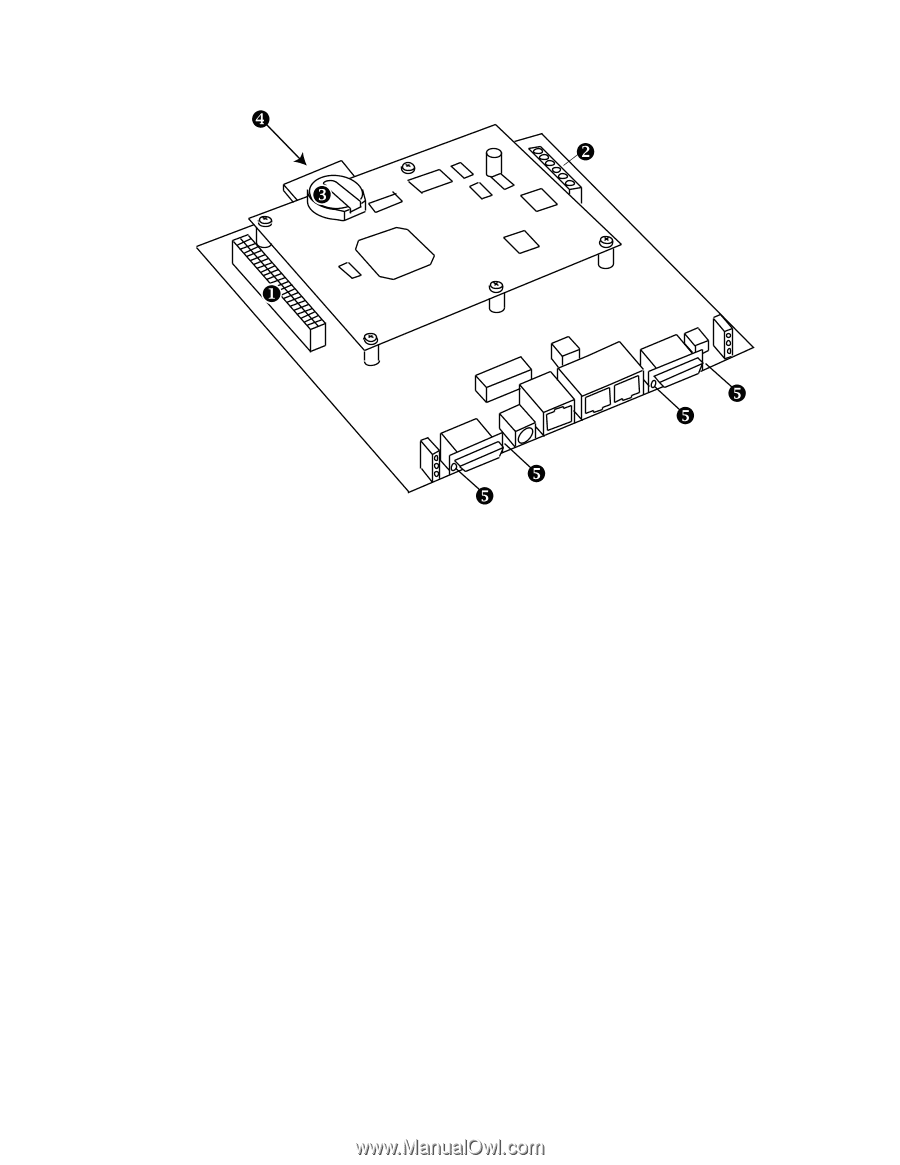
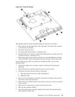
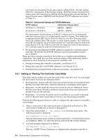
Figure 8-8: Controller Module [ Y Z X \ \ \ \ The following features of the controller module are relevant to servicing: 1. The connector for the ribbon data cable. The other end of this cable connects to the switch card module. 2. The power cable connector. 3. The replaceable lithium battery. (SeeSection 8.6). 4. Below the battery is a slot for a replaceable flash memory card that stores the controller firmware. (SeeSection 8.7). 5. The location of the 4 hexagonal screwlocks in each of the DB9 ports (labeled VGA and COM 1). These screwlocks secure the controller card in the chassis. Use the following procedure to replace the controller module, carry out the following steps: 1. Unpack the replacement controller module, retaining all the packaging materials 2. Switch off the power and disconnect the power cord at the inlet. 3. Disconnect only the following cables (if connected): a. Management terminal serial cable and keyboard. b. Ethernet cable 4. Remove the four hexagonal screwlocks and washers located on either side of the monitor and serial connectors. 5. Remove the fan and PSU module as described in Section 8.3 and put it aside in a safe location. 6. Disconnect the internal power cable and data ribbon cable. 7. Slide out the controller module. 8. Insert the replacement controller module and reconnect the internal power cable and data ribbon cable. Maintenance of the 16/32-Port Interconnect 8-9
-
 1
1 -
2
-
3
-
4
-
5
-
6
-
7
-
8
-
9
-
10
-
11
-
12
-
13
-
14
-
15
-
16
-
17
-
18
-
19
-
20
-
21
-
22
-
23
-
24
-
25
-
26
-
27
-
28
-
29
-
30
-
31
-
32
-
33
-
34
-
35
-
36
-
37
-
38
-
39
-
40
-
41
-
42
-
43
-
44
-
45
-
46
-
47
-
48
-
49
-
50
-
51
-
52
-
53
-
54
-
55
-
56
-
57
-
58
-
59
-
60
-
61
-
62
-
63
-
64
-
65
-
66
-
67
-
68
-
69
-
 70
70 -
 71
71 -
 72
72 -
 73
73 -
 74
74 -
 75
75 -
 76
76 -
 77
77 -
 78
78 -
 79
79 -
 80
80 -
81
-
82
-
83
-
84
-
85
-
86
-
87
-
88
-
89
-
90
-
91
-
92
-
93
-
94
-
95
-
96
-
97
-
98
-
99
-
100
-
101
-
102
-
103
-
104
-
105
-
106
-
107
-
108
-
109
-
110
-
111
-
112
-
113
-
114
-
115
-
116
-
117
-
118
-
119
-
120
-
121
-
122
-
123
-
124
-
125
-
126
-
127
-
128
-
129
-
130
-
131
-
132
-
133
-
134
-
135
-
136
-
137
-
138
-
139
-
140
-
141
-
142
-
143
-
144
-
145
-
146
-
147
-
148
-
149
-
150
-
151
-
152
-
153
-
154
-
155
-
156
-
157
-
158
-
159
-
160
-
161
-
162
-
163
-
164
-
165
-
166
 |
 |