HP Cluster Platform Interconnects v2010 Quadrics QsNetII Interconnect - Page 88
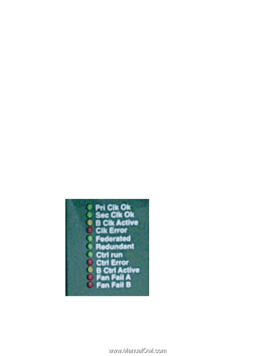
QM503 Timing and Control Card LEDs
 |
View all HP Cluster Platform Interconnects v2010 manuals
Add to My Manuals
Save this manual to your list of manuals |
Page 88 highlights
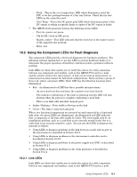
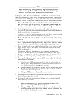
Depending on the type of switch card installed in a slot, its port LEDs show the following status: - The status of the link between the interconnect and the QM500 PCI card in the node - The status of the link between the node-level interconnect and the top-level interconnect in a federated cluster. • The QM503 controller card has the following status LEDs as shown in Figure 10-1, callout 1: - Pri Clk OK (green) - Sec Clk OK (green) - B Clock active, (amber) - Clk Error, (red) - Federated, (green) - Redundant, (green) - Ctrl Run, (green) - Cntrl Error, (red) - B Cntrl Active, (amber) - Fan Fail A, (red) - Fan Fail B, (red) - Ethernet (network) port, amber and green (green indicates a good connection, amber flashes to indicate that data traffic is flowing), See Figure 10-1, callout 3 for the location of this port. With the exception of the network port, the controller LED labels are illustrated in Figure 10-2. Figure 10-2: QM503 Timing and Control Card LEDs • The QS5A power supply has the following status LEDs, which are all red: - AC (alternating current in) Good - This the AC power good LED which illuminates green if the AC inlet supply is working or red if the supply is faulty. - DC (direct current out) Good - This LED illuminates red if the AC inlet supply or the DC output is not within acceptable limits. 10-2 Using Component LEDs
-
 1
1 -
2
-
3
-
4
-
5
-
6
-
7
-
8
-
9
-
10
-
11
-
12
-
13
-
14
-
15
-
16
-
17
-
18
-
19
-
20
-
21
-
22
-
23
-
24
-
25
-
26
-
27
-
28
-
29
-
30
-
31
-
32
-
33
-
34
-
35
-
36
-
37
-
38
-
39
-
40
-
41
-
42
-
43
-
44
-
45
-
46
-
47
-
48
-
49
-
50
-
51
-
52
-
53
-
54
-
55
-
56
-
57
-
58
-
59
-
60
-
61
-
62
-
63
-
64
-
65
-
66
-
67
-
68
-
69
-
70
-
71
-
72
-
73
-
74
-
75
-
76
-
77
-
78
-
79
-
80
-
81
-
82
-
 83
83 -
 84
84 -
 85
85 -
 86
86 -
 87
87 -
 88
88 -
 89
89 -
 90
90 -
 91
91 -
 92
92 -
 93
93 -
94
-
95
-
96
-
97
-
98
-
99
-
100
-
101
-
102
-
103
-
104
-
105
-
106
-
107
-
108
-
109
-
110
-
111
-
112
-
113
-
114
-
115
-
116
-
117
-
118
-
119
-
120
-
121
-
122
-
123
-
124
-
125
-
126
-
127
-
128
-
129
-
130
-
131
-
132
-
133
-
134
-
135
-
136
-
137
-
138
-
139
-
140
-
141
-
142
-
143
-
144
-
145
-
146
-
147
-
148
-
149
-
150
-
151
-
152
-
153
-
154
-
155
-
156
-
157
-
158
-
159
-
160
-
161
-
162
-
163
-
164
-
165
-
166
 |
 |