HP Cluster Platform Interconnects v2010 Quadrics QsNetII Interconnect - Page 49
Installation and Maintenance of the 128-Port, Interconnect
 |
View all HP Cluster Platform Interconnects v2010 manuals
Add to My Manuals
Save this manual to your list of manuals |
Page 49 highlights
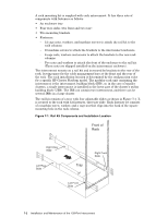
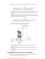
7 Installation and Maintenance of the 128-Port Interconnect This chapter describes how to install modules and service the 128-port interconnect. The installation procedures are similar for all interconnect configurations used in the HP Cluster Platform. Where the procedures differ, the switch card (module) or midplane type is mentioned explicitly. 7.1 Installing the Interconnect Enclosure This chapter describes how to install an interconnect that can connect up to 64 (QM540 midplane) or 128 (QM542 midplane) nodes. Each of these nodes must have a Quadrics QM500 network adapter installed. The installation procedure is as follows: 1. Unpack the interconnect and secure it in the designated location in the position in the HP model 10642 rack. (Although the illustrations in this section show a populated enclosure, it is easier to install the enclosure first and populate it with modules later). 2. If any component modules (such as switch cards) are shipped separately, install them in the following order: a. QM501 (switch card) modules and QM502 (switch card) modules (QM540 Midplane). b. QM511C modules and QM511L modules (QM542 Midplane). c. QM503 controller cards. d. QM561 power supply units. e. QM562 fan trays. f. Blank cards 3. Power up the interconnect. 4. Connect link cables from the interconnect to each of the QM500 network adapters. 5. Verify that the system is working correctly by using appropriate diagnostic commands. Observe electrostatic damage precautions when installing and removing any modules. 7.2 Installing the Interconnect Enclosure in The Rack Caution Two persons are needed lift the enclosure into the rack. Always install components into the lowest locations first. Ensure that the rack is stable before beginning work. HP Cluster Platform racks must be connected together by using the standard baying kit, as described in the Site Planning Guide. Installation and Maintenance of the 128-Port Interconnect 7-1
-
 1
1 -
2
-
3
-
4
-
5
-
6
-
7
-
8
-
9
-
10
-
11
-
12
-
13
-
14
-
15
-
16
-
17
-
18
-
19
-
20
-
21
-
22
-
23
-
24
-
25
-
26
-
27
-
28
-
29
-
30
-
31
-
32
-
33
-
34
-
35
-
36
-
37
-
38
-
39
-
40
-
41
-
42
-
43
-
 44
44 -
 45
45 -
 46
46 -
 47
47 -
 48
48 -
 49
49 -
 50
50 -
 51
51 -
 52
52 -
 53
53 -
 54
54 -
55
-
56
-
57
-
58
-
59
-
60
-
61
-
62
-
63
-
64
-
65
-
66
-
67
-
68
-
69
-
70
-
71
-
72
-
73
-
74
-
75
-
76
-
77
-
78
-
79
-
80
-
81
-
82
-
83
-
84
-
85
-
86
-
87
-
88
-
89
-
90
-
91
-
92
-
93
-
94
-
95
-
96
-
97
-
98
-
99
-
100
-
101
-
102
-
103
-
104
-
105
-
106
-
107
-
108
-
109
-
110
-
111
-
112
-
113
-
114
-
115
-
116
-
117
-
118
-
119
-
120
-
121
-
122
-
123
-
124
-
125
-
126
-
127
-
128
-
129
-
130
-
131
-
132
-
133
-
134
-
135
-
136
-
137
-
138
-
139
-
140
-
141
-
142
-
143
-
144
-
145
-
146
-
147
-
148
-
149
-
150
-
151
-
152
-
153
-
154
-
155
-
156
-
157
-
158
-
159
-
160
-
161
-
162
-
163
-
164
-
165
-
166
 |
 |
